Gasoline Powered Generator Owner’s Manual Max Tool Customer Service customer_service@maxtool.com or call 1-800-629-3325 (option 3) Monday -Friday 6am to 6pm PST Product Support (Product: information, application, service info & warranty questions) support@maxtool.com or call 1-800-629-3325 (option 3) Monday -Friday 6am to 6pm PST This manual provides information regarding the operation and maintenance of these products. We have made every effort to ensure the accuracy of the information in this manual.
FEATURES • Durable 7.0 Hp, Air Cooled Overhead Valve Engine. • Heavy Duty Steel Frame with Four Point Fully Isolated Motor Mounts for Smooth and Quiet Operation. • Full Power Panel with Engine Shutoff Switch, Volt Meter, Circuit Breaker and Power Outlets. • (2) Fully Protected 120V Standard Household Outlets & (1) High Amperage 120V Twist-Lock Outlet. • 8 Hour Run Time. • All Steel 4.0 Gal. Fuel Tank with EZ-Read Gauge. • Low Oil Shut-Off Protects Engine. • Super Quiet Muffler Reduces Engine Noise.
TABLE OF CONTENTS GENERAL SAFETY PROCEDURES............................................................................................................. 1 PACKAGE CONTENTS ................................................................................................................................. 4 GENERATOR COMPONENTS...................................................................................................................... 5 PREPARING THE GENERATOR FOR USE ...................................
GENERAL SAFETY PROCEDURES Please familiarize yourself with the following safety symbols and words: is used with one of the safety words (DANGER, CAUTION, or The safety alert symbol WARNING) to alert you to hazards. Please pay attention to these hazard notices both in this manual and on the generator. DANGER: Indicates a hazard that will result in serious injury or death if instructions are not followed.
WARNING: This generator produces powerful voltage, which can result in electrocution. • ALWAYS ground the generator before using it (see the "Grounding the Generator" portion of the "PREPARING THE GENERATOR FOR USE" section). • Generator should only be plugged into electrical devices, either directly or with an extension cord. NEVER connect to a building electrical system without a qualified electrician. Such connections must comply with local electrical laws and codes.
In addition to the above safety notices, please familiarize yourself with the safety and hazard markings on the generator.
PACKAGE CONTENTS Your generator comes with the items listed below. Please check to see that all of the following items may be included with your generator, depending on your generator model.
GENERATOR COMPONENTS Please familiarize yourself with the locations and functions of the various components and controls of your generator. (1) Air cleaner - a removable, cleanable, sponge-like element that limits the amount of dirt pulled into the engine. (2) Choke lever - Adjusts the amount of air let into the engine. (3) Fuel Gauge - Indicates the amount of fuel in the tank. (4) Fuel Cap - Access to the fuel tank for adding fuel.
(11) Oil Drain Bolt - Location for used for draining the oil. (12) Engine Switch - Used to start/stop engine. (13) Recoil Starter - Pull-cord for starting engine. (14) Fuel Filter Cup - Traps dirt and water from fuel before it enters the engine. (15) Fuel valve - Allows fuel to enter engine. (16) Spark plug - Provides proper engine ignition. (17) Muffler - Reduces engine noise.
crankcase. You will know the crankcase is full when the oil level has reached the lower lip of the opening you have just poured the oil into (see figure 3). 4. Replace oil filler cap. Figure 2- Unscrewing the oil cap Figure 3 - Adding oil Step 2- Add Gasoline WARNING: Gasoline and gas fumes are highly flammable. • Do not fill tank near an open flame. • Do not overfill. Always check for fuel spills.
A generally acceptable grounding wire is a stranded copper wire. This grounding wire should be connected at the other end to a copper or brass-grounding rod that is driven into the end. Grounding codes can vary by location. Please contact a local electrician to check the grounding regulations for your area.
generator ). Always check for fuel spills. IMPORTANT: • Use only UNLEADED gasoline with an octane rating of 87 or higher. • Do not use old gas. • Never use an oil/gasoline mixture. • Avoid getting dirt or water in the fuel tank. • Never store generator for extended periods of time with fuel in the tank. STARTING THE GENERATOR CAUTION: Disconnect all electrical loads from the generator before attempting to start. To start your generator, perform the following steps: 1.
USING THE GENERATOR Once you have allowed the engine to run for several minutes, you may connect electrical devices to the generator. AC Usage You may connect electrical devices running on AC current according to their wattage requirements. The chart in figure 9 shows the rated and surge wattage of your generator according to its model number. The rated wattage corresponds to the maximum wattage the generator can output continuously.
Tool or Appliance Electric water heater (40 gal) Hot plate Saw-radial arm Electric stove Saw-circular Air compressor (1HP) Window air conditioner Saw-miter Microwave Well water pump Reciprocating saw Sump pump Refrigerator freezer Furnace blower Computer Electric drill Television Deep freezer Garage door opener Stereo Box fan Clock radio Security system DVD player/VCD Common light bulb Rated (Running) Watts 4000 2500 2000 1500 1500 1500 1200 1200 1000 1000 960 800 800 800 800 600 500 500 480 400 300 300 18
Once you have determined what electrical devices you will be powering with the generator, connect these devices according to the following procedure: 1. Plug in each electrical device with the device turned off. a. NOTE: Be sure to attach appliances to the correct receptacle (outlet). Connect standard 120 Volt, single phase, 60 Hz loads only to the 120 Volt receptacle. 2. Switch the circuit breaker to the "ON" position. 3.
STOPPING THE GENERATOR To stop the generator: 1. Turn off, then unplug all connected electrical devices. 2. Switch the circuit breaker to the "OFF” position. 3. Allow the generator to run for several more minutes with no electrical devices connected. This helps stabilize the temperature of the generator. 4. Set the engine switch to the "OFF” position. 5. Turn the fuel valve to the "OFF” position. WARNING: Allow the generator to cool for several minutes before touching areas that become hot during use.
Checking the Oil The generator is equipped with an automatic shutoff to protect it from running on low oil. Nonetheless, you should check the oil level of the generator before each use to ensure that the generator crankcase has a sufficient amount. To check the oil level: 1. Make sure the generator is on a level surface. 2. Unscrew the oil filler/dipstick cap (see figure 14). 3. With a dry cloth, wipe the oil off of the stick on the inside of the cap. 4.
It is only necessary to drain the oil from the crankcase if it has become contaminated with water or dirt. In this case, you can drain the oil from the generator according to the following steps: 1. Place a bucket underneath the generator to catch oil as it drains. 2. Using a 10 mm hex wrench, unscrew the oil drain plug, which is located on the crankcase underneath the oil filler/dipstick cap (see figure 16). Allow all the oil to drain from the generator. 3.
Fuel Filter Cup Cleaning The fuel filter cup is a small well underneath the fuel valve. It helps to trap dirt and water that may be in your fuel tank before it can enter the engine. To clean the fuel filter cup: 1. Turn the fuel valve to the "OFF” position. 2. Unscrew the fuel filter cup from the fuel valve using a wrench. Turn the valve toward you to unscrew (see figure 19). 3. Clean the cup of all sediment. Using a rag or brush. 4. Reinstall the fuel filter cup.
Emptying the Gas Tank Before storing your generator for extended periods of time, you should drain your generator of gasoline. To drain the generator of gas: 1. Turn the fuel valve to the "OFF” position. 2. Remove the fuel filter cup (see "Removing the Fuel Filter Cup" earlier in this section. 3. Empty the fuel filter cup of any fuel. 4. With a receptacle underneath the generator to catch the gas, turn the fuel valve to the "ON" position. Drain all the gas from the generator. 5.
TROUBLESHOOTING Problem Engine will not start Engine will not start (continued from page 19) Engine runs but there is no electrical output Generator runs but does not support all electrical devices connected. Cause Engine switch is set to “OFF”. Fuel valve is turned to “CLOSED”. Choke is open. Engine is out of gas. Engine is filled with contaminated or old gas Spark plug is dirty. Spark plug is broken. Generator is not on level surface. Oil is low Circuit breaker is off. Bad connecting wires/cables.
INSTALLING THE OPTIONAL WHEEL AND HANDLE KIT If you have purchased the optional wheel and handle kit for your unit, please follow the instructions below. If you have not purchased the optional wheel and handle kit, skip this section. 1. Place the bottom of the generator cradle on a flat, even surface. Te mporarily place unit on blocks to ease assembly. 2. Secure the support leg to the cradle with cap screws (M8 x 16) and lock nut s (M8) (see figure 22 ). 3.
CHANGE THE CARBON-BRUSH CHANGE THE AVR 20 20
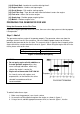
WIRING DIAGRAM (DS4000S) Main coil Sub-fied coil Field coil Generator wiring diagram R W W R Bu Bu R W W R Bu Bu R W Y/G V ~ W R Bl Bl R W Y/G Socket NEMA L5-30R Spark Ignition coil plug Oil alert unit Bl Breaker 30-18A-1P Control panel block Bl/W fuel protector Socket NEMA 5-20R Y/G Y/G Engine block 21
EXPLODED VIEW AND PARTS LIST (DS4000S) 84 22
Ite m Part Qt y Description Ite m Part Qt y Description Set Pin, 10×14 1 DJ168F-16121-K 1 Recoil Starter 43 DJ168F-11009-A 2 2 GBT5787-B6-8 4 Bolt Flange M6×8 44 GB276-89-6205 2 3 DJ168F-16118 1 Grommet drain hole 45 DJ168F-18500-A 1 Spark Plug F7TC 4 DJ168F-16100-F.
24
Ite Part m 85 DF2500H-31201-A Qt Description y 2 Bottom rubber A Ite Part m 127 14306 86 DF2500H-31202-A 2 Bottom rubber B 87 GBT6177-N-8 Qty Description 1 Fuel filler cap comp 128 14303 1 Fuel sensor 4 Flange nut M8 129 GBT819-B-5 2 Screw M5×10 88 GBT889-N-8 10 Flange nut M8 130 14313 1 GASKET,FUEL SENSOR 89 DF2500H-14304-A 1 Rubber Screws, Fuel Tank 131 14311 4 Washer 90 34107 1 Earth terminal set 132 14305 4 Collar 91 34206-008 1 Circuit breaker 133 14304 4 Cushion 92