DS4000WGE Gasoline Generator/Welder Owner’s Manual Max Tool Customer Service customer_service@maxtool.com or call 1-800-629-3325 (option 3) Monday -Thursday 6am to 7pm, Friday - Saturday 6am to 3pm. PST Product Support (Product: information, application, service info & warranty questions) support@maxtool.com or call 1-800-629-3325 (option 3) Monday -Thursday 6am to 7pm, Friday - Saturday 6am to 3pm. PST This manual provides information regarding the operation and maintenance of these products.
WARNING: The engine exhaust from this product contains chemicals known to the State of California to cause cancer, birth defects or other reproductive harm. WARNING: The generator is a potential source of electrical shock if misused. Do not expose the generator to moisture, rain or snow. Do not let the generator get wet, and do not operate it with wet hands. Keep this owner's manual handy, so you can refer to it at any time.
A FEW WORDS ABOUT SAFETY Your safety and the safety of others is very important. And using this generator/Welder safely is an important responsibility. To help you make informed decisions about safety, we have provided operating procedures and other information on labels and in this manual. This information alerts you to potential hazards that could hurt you or others. Of course, it is not practical or possible to warn you about all the hazards associated with operating or maintaining a generator/Welder.
CONTENTS SAFETY.......................................................................................................................................................... 1 Safety Label Locations................................................................................................................................ 1 Safety Information....................................................................................................................................... 1 COMPONENT INDENTIFICATION .....
SAFETY SAFETY LABEL LOCATIONS These labels warn you of potential hazards that can cause serious injury. Read them carefully. If a label comes off or becomes hard to read, contact your Generator dealer for a replacement. SAFETY INFORMATION Our generator/welders are designed to give safe and dependable service if operated according to instructions. Read and understand this owner's manual before operating your generator/welder.
— Keep flammable materials away from the generator/welder. • The muffler becomes very hot during operation and remains hot for a while after stopping the engine. Be careful not to touch the muffler while it is hot. Let the engine cool before storing the generator/welder indoors. • Gasoline is extremely flammable and is explosive under certain conditions. Do not smoke or allow flames or sparks where the generator/welder is refueled or where gasoline is stored.
COMPONENT IDENTIFICATION • Record the engine and frame serial numbers for your future reference. Refer to these serial numbers when ordering parts, and when making technical or warranty inquiries.
CONTROLS Engine Switch To start and stop the engine. Switch position: OFF: To stop the engine. ON: To run the engine. Recoil Starter To start the engine, pull the starter grip lightly until resistance is felt, then pull briskly. NOTICE: Do not allow the starter grip to snap back against the engine. Return it gently to prevent damage to the starter.
Fuel Valve Lever The fuel valve is located between the fuel tank and carburetor. When the fuel valve lever is in the ON position, fuel is allowed to flow from the fuel tank to the carburetor. Be sure to return the fuel lever to the OFF position after stopping the engine. Choke Rod The choke is used to provide an enriched fuel mixture when starting a cold engine. It can be opened and closed by operating the choke rod manually. Pull the rod out toward CLOSED to enrich the mixture for cold starting.
Oil Alert System The Oil Alert System is designed to prevent engine damage caused by an insufficient amount of oil in the crankcase. Before the oil level in the crankcase can fall below a safe limit, the oil alert system will automatically stop the engine (the engine switch will remain in the ON position). If the engine stops and will not restart, check the engine oil level before troubleshooting in other areas.
Welding Cable Terminal A separate terminal is provided for connection to the welding cable. CAUTION: Failure to use the proper gauge cable may lead to painful burns and/or damage to equipment. Welding Current Adjusting System For best results, it is essential the current be adjusted properly according to the thickness of the materials to be welded and method of welding.
GENERATOR/WELDER USE Connections To A Building Electrical System Connections for standby power to a buildings electrical system must be made by a qualified electrician. The generator/welder power connection must be isolate from the utility power, and must comply with all applicable laws and electrical codes. A transfer switch, which isolates the generator/welder power from utility power, is available through authorized generator dealers.
• For continuous operation, do not exceed the rated load capacity (W-190: 2.0 KVA). In either case, be sure to consider the total power requirements of all connected appliances. Do not exceed the current limit specified for any one receptacle. Substantial overloading will switch off the circuit breaker. Marginal overloading may not switch off the circuit breaker, but it will shorten the service life of the generator/welder.
Selecting the Correct Welding Current Measure the thickness of the metal you are welding and then refer to the table below to select the proper electrode size and current setting PLATE THICKNESS IN ELECTRODE DIAMETER IN CURRENT INCHES INCHES SETTING UP TO 3/16" 1/16" 50-100 UP TO 1/4" 3/32" 100-150 ABOVE 1/8" 1/8" 125-175 ABOVE 1/4" 5/32" 150-200 Always make a sample weld on a piece of scrap material to be sure you have chosen the correct electrode and current setting.
Polarity Selection The welding terminals are labeled "+" (positive) and "-" (negative). Changing the polarity of the cables will affect the weld. The correct polarity selection is dependent on the type of electrode you are using and the type of material you are welding; refer to the electrode manufacturer's recommendations for best results. For straight polarity, attach the electrode cable to the negative terminal, and attach the ground cable to the positive terminal.
PRE-OPERATION CHECK Engine oil NOTICE: Engine oil is the major components affecting engine performance and service life. Non-detergent and 2-stroke engine oils will damage the engine and is not recommended. Check the oil level BEFORE EACH USE. When checking the oil be sure the generator is on a level surface with the engine stopped. Use 4-stroke motor oil that meets or exceeds the requirements for API service classification SJ.
WARNING: • Gasoline is extremely flammable and is explosive under certain conditions. • Refuel in a well-ventilated area with the engine stopped. Do not smoke or allow flames or sparks in the area where the engine is refueled or where gasoline is stored. • Do not overfill the fuel tank (there should be no fuel in the filler neck) .After refueling, make sure the tank cap is closed properly and securely. Be careful not to spill fuel when refueling. Spilled fuel or fuel vapor may ignite.
Some conventional gasolines are being blended with alcohol or an ether compound. These gasolines are collectively referred to as oxygenated fuels. To meet clean air standards, some areas of the United States and Canada use oxygenated fuels to help reduce emissions. If you use an oxygenated fuel, be sure it is unleaded and meets the minimum octane rating requirement. Before using an oxygenated fuel, try to confirm the fuel's contents. Some states/provinces require this information to be posted on the pump.
STARTING THE ENGINE/STOPPING THE ENGINE Starting the Engine 1. Make sure that the AC circuit breaker is in the OFF position, and that there are no welding cables attached to the DC terminals. The generator may be hard to start if a load is connected. 2. Turn the fuel valve lever to the ON position. 3. Pull the choke rod to the CLOSE position. 4. Make sure the auto-throttle switch is in the OFF position, or more time will be required for warm-up. 5. Move the engine switch to the ON position. 6.
MAINTENANCE The Importance of Maintenance Good maintenance is essential for safe, economical, and trouble-free operation. It will also help reduce air pollution. WARNING: Improper maintenance, or failure to correct a problem before operation, can cause a malfunction in which you can be seriously hurt or killed. Always follow the inspection and maintenance recommendations and schedules in this owner's manual.
• To reduce the possibility of fire or explosion, be careful when working around gasoline. Use only a nonflammable solvent, not gasoline, to clean parts. Keep cigarettes, sparks, and flames away from all fuel-related parts. Remember that your servicing dealer knows your generator best and is fully equipped to maintain and repair it. To ensure the best quality and reliability, use only new, genuine parts or their equivalents for repair or replacement.
with EPA and California emission regulations. We recommend the use of genuine parts whenever you have maintenance done. These original-design replacement parts are manufactured to the same standards as the original parts, so you can be confident of their performance. The use of replacement parts that are not of the original design and quality may impair the effectiveness of your emission control system.
Maintenance Schedule REGULAR SERVICE PERIOD (3) ITEM Perform at every indicated month or operating hour interval, whichever comes first • Engine oil Check level Change • Air filter Check Clean • Sediment cup Clean • Spark plug Check-adjust Replace • Spark arrester Clean • Idle speed Check-adjust • Valve clearance Check-adjust • Combustion chamber Clean • • • Fuel tank Fuel filter Fuel tube Each use First month or 12 Hrs Every 3 month or 50 Hrs Every 6 month or 100 Hrs Every year or 300 Hrs O O O O
Wash your hands with soap and water after handling used oil. Please dispose of used motor oil in a manner that is compatible with the environment. We suggest you take it in a sealed container to your local service station or recycling center for reclamation. Do not throw it in the trash or pour it on the ground, or down a drain. Air Cleaner Service A dirty air cleaner will restrict air flow to the carburetor. To prevent carburetor malfunction, service the air cleaner regularly.
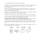
Fuel Sediment Cup Cleaning The sediment cup prevents dirt or water which may be in the fuel tank from entering the carburetor. If the engine has not been run for a long time, the sediment cup should be cleaned. 1. Turn the fuel valve lever to the OFF position. Remove the sediment Cup, O-ring, and filter. 2. Clean the sediment cup, O-ring, and filter in nonflammable or high flashpoint solvent. 3. Reinstall the filter, O-ring, and sediment cup. 4. Turn the fuel valve lever ON and check for leaks.
4. Visually inspect the spark plug. Discard it if the insulator is cracked or chipped. Clean the spark plug with a wire brush if it is to be reused. 5. Measure the plug gap with a feeler gauge. Correct as necessary by carefully bending the side electrode. The gap should be: 0.028-0.031 in (0.70--0.80 mm) 7. Check that the spark plug washer is in good condition, and thread the sparkplug in by hand to prevent cross-threading. 8.
TRANSPORTING STORAGE When transporting the generator/welder, turn the engine switch and the fuel valve OFF and keep the generator/welder level to prevent fuel spillage. Fuel vapor or spilled fuel may ignite. WARNING: Contact with a hot engine or exhaust system can cause serious burns or fires. Let the engine cool before transporting or storing the generator/welder. Take care not to drop or strike the generator/welder when transporting. Do not place heavy objects on the generator/welder.
2. Change the engine oil. 3. Remove the spark plug, and pour about a tablespoon of clean engine oil into the cylinder. Crank the engine several revolutions to distribute the oil, and then reinstall the spark plug. 4. Slowly pull the starter grip until resistance is felt. At this point, the piston is coming up on its compression stroke and both the intake and exhaust valves are closed. Storing the engine in this position will help to protect it from internal corrosion.
WIRING DIAGRAM 29
SPECIFICATION Dimensions Model Length x Width x Height Dry weight DS4000WGE 29 x 22 x 22 in (712 x 540 x 540mm) 217.8 lb (98kg) Engine Model Engine type Displacement (Bore x Stroke) Compression ratio Engine speed Cooling system Ignition system Oil capacity Fuel tank capacity Spark plug Noise Level DS190FE 4-stroke, overhead valve, single cylinder 25.6cu in (419cc) 3.54 x 2.6 in (90 x 66mm) 8.0:1 3.600 rpm Forced air Transistorized magneto 1.16 US. Qt. (1.1L, 37fl oz.) 6.
WHEEL KIT Handle/Wheel support and wheel kit.
EXPLODED VIEW AND PARTS LIST 32
Item Part 1 Qty Description Item Part Qty Description 1 Gasoline engine 42 14400 1 Fuel sensor 2 15100 1 Frame comp 43 GB 819-95 2 Screw M5x10 3 15002 2 Bottom rubber A 44 14410 1 Casket fuel tank 4 15003 2 Bottom rubber B 45 GB5787-86 5 Flange bolt M6x25 5 GB6177-86 16 Flange nut M8 46 14022 4 Washer 6 GB802-88 4 Flange nut M6 47 14005 4 Collar 7 41350 4 Cushion, frame 48 14001 4 Cushion 8 GB5787-86 12 Bolt M6x12 49 14004 1 Outlet pipe4
Item 71 72 73 74 Part Qty 21100 1 GB5787-86 12310 GB5787-86 Description Item Part Qty Description Starter comp, recoil 115 22000 1 Stay assembly choke 3 Flange bolt M6x8 116 12012 1 Grommet fender 1 Fan, cover comp 117 23000 1 Carburetor assembly 13 Flange bolt M6x12 118 23002 1 Packing, carburetor 23001 1 Insulator, carburetor 4 Flange nut M6 75 19003 1 Shroud comp 119 76 12302 3 Clip.
159 160 161 162 11206 GB5789-86 12100 GB5789-86 2 Nut, pivot adjusting 169 13105 2 Clip, piston pin 7 Flange bolt M8x40 170 13101 1 Piston 1 Crankcase cover 171 13104 1 Pin, piston 3 Flange bolt M5x10 172 13106 1 Connecting rod assembly 163 12301 1 Fan cover 173 17220 1 Control assembly 164 121102 1 Cap assembly oil filler 174 17001 1 Spring, governor 165 12230 1 Governor kit 175 17002 1 Spring, throttle return 166 12214 1 Packing, case cover 176 17004