Gasoline Powered Generator Owner’s Manual Product Support (Product: information, application, service info & warranty questions) product_support@durostarusa.com or call 1-800-629-3325 (option 3) Monday -Thursday 6am to 6pm, Friday 6am to 5pm. PST This manual provides information regarding the operation and maintenance of these products. We have made every effort to ensure the accuracy of the information in this manual. We reserve the right to change this product at any time without prior notice.
FEATURES • Durable 7 Hp, Air Cooled Overhead Valve Engine. • Heavy Duty Steel Frame with Four Point Fully Isolated Motor Mounts for Smooth and Quiet Operation. • Wheel and Handle Kit for Easy Transporting. • Full Power Panel with Engine Shutoff Switch, Volt Meter, Circuit Breaker and Power Outlets. • (2) Fully Protected 120V Outlets & (1) 120V/240V Twist-Lock Outlets. • 8 Hour Run Time. • All Steel 4.0 Gal. Fuel Tank with EZ-Read Gauge. • Low Oil Shut-Off Protects Engine.
TABLE OF CONTENTS GENERAL SAFETY PROCEDURES............................................................................................................. 1 PACKAGE CONTENTS ................................................................................................................................. 4 GENERATOR COMPONENTS...................................................................................................................... 5 PREPARING THE GENERATOR FOR USE ...................................
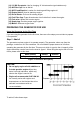
GENERAL SAFETY PROCEDURES Please familiarize yourself with the following safety symbols and words: is used with one of the safety words (DANGER, CAUTION, or The safety alert symbol WARNING) to alert you to hazards. Please pay attention to these hazard notices both in this manual and on the generator. DANGER: Indicates a hazard that will result in serious injury or death if instructions are not followed.
WARNING: This generator produces powerful voltage, which can result in electrocution. • ALWAYS ground the generator before using it (see the "Grounding the Generator" portion of the "PREPARING THE GENERATOR FOR USE" section). • Generator should only be plugged into electrical devices, either directly or with an extension cord. NEVER connect to a building electrical system without a qualified electrician. Such connections must comply with local electrical laws and codes.
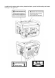
In addition to the above safety notices, please familiarize yourself with the safety and hazard markings on the generator.
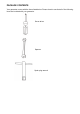
PACKAGE CONTENTS Your generator comes with the items listed below. Please check to see that all of the following items are included with your generator.
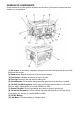
GENERATOR COMPONENTS Please familiarize yourself with the locations and functions of the various components and controls of your generator. (1) Air cleaner- a removable, cleanable, sponge-like element that limits the amount of dirt pulled into the engine. (2) Choke lever- Adjusts the amount of air let into the engine. (3) Fuel Gauge- Indicates the amount of fuel in the tank. (4) Fuel Cap- Access to the fuel tank for adding fuel.
(11) 12V DC Receptacle- Use for charging 12 Volt automotive-type batteries only. (12) Oil Filler Cap- Use to Add oil. (13) Oil Fill and Dipstick- Location for checking and filling engine oil. (14) Engine Switch- Used to start/stop engine. (15) Recoil Starter- Pull-cord for starting engine. (16) Fuel Filter Cup- Traps dirt and water from fuel before it enters the engine. (17) Fuel valve- Allows fuel to enter engine. (18) Spark plug- Provides proper engine ignition. (19) Muffler- Reduces engine noise.
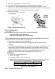
1. Make sure the generator is on a level surface. 2. Unscrew the oil filler/dipstick cap from the engine as shown in figure 2. 3. Using a funnel, add the appropriate amount of oil, as found in figure 1, into the crankcase. You will know the crankcase is full when the oil level has reached the lower lip of the opening you have just poured the oil into (see figure 3). 4. Replace oil filler cap.
WARNING: Failure to properly ground the generator can result in electrocution. Ground the generator by tightening the grounding nut against a grounding wire (see figure 5). A generally acceptable grounding wire is a No. 12 AWG (American Wire Gauge) stranded copper wire. This grounding wire should be connected at the other end to a copper or brass-grounding rod that is driven into the end. Grounding codes can vary by location.
• • • Do not fill tank near an open flame. Always allow the engine to cool for several minutes before refueling. Do not overfill (check the "Specifications" section for the tank capacity of your generator). Always check for fuel spills. IMPORTANT: • • • • • Use only UNLEADED gasoline with an octane rating of 87 or higher. Do not use old gas. Never use an oil/gasoline mixture. Avoid getting dirt or water in the fuel tank. Never store generator for extended periods of time with fuel in the tank.
USING THE GENERATOR Once you have allowed the engine to run for several minutes, you may connect electrical devices to the generator. AC Usage You may connect electrical devices running on AC current according to their wattage requirements. The chart in figure 9 shows the rated and surge wattage of your generator according to its model number. The rated wattage corresponds to the maximum wattage the generator can output on a continuous basis.
If these specifications are not available you may estimate the Watts required by your device by using the chart in figure 10.
Once you have determined what electrical devices you will be powering with the generator, connect these devices according to the following procedure: 1. Plug in each electrical device with the device turned off. a. NOTE: Be sure to attach appliances to the correct receptacle (outlet). Connect standard 120 Volt, single phase, 60 Hz loads only to the 120 Volt receptacle. b.
Device Requirements Max. Cord Length (ft) by Wire Gauge Watts Watts #8 wire #10 wire #12 wire #14 wire #16 wire (120V) (240V) 2.5 300 600 NR 1000 600 375 250 5 600 1200 NR 500 300 200 125 7.
If your generator is electric start model, once running, it will charge the battery on the generator automatically. While charging, you can see the indication light is on, after the battery is full, the light will turn off. STOPPING THE GENERATOR To stop the generator: 1. Turn off, then unplug all connected electrical devices. 2. Switch the circuit breaker to the "OFF” position. 3. Allow the generator to run for several more minutes with no electrical devices connected.
- A vacuum - Pressurized air Never clean your generator with a bucket of water or a hose. Water can get inside the working pats of the generator and cause a short circuit or corrosion. Checking the Oil The generator is equipped with an automatic shutoff to protect it from running on low oil. Nonetheless, you should check the oil level of the generator before each use to ensure that the generator crankcase has a sufficient amount. To check the oil level: 1. Make sure the generator is on a level surface. 2.
Model number Engine oil capacity DS4400 DS4400E 20 fluid oz. Figure 15- Engine Oil Capacity. It is only necessary to drain the oil from the crankcase, other than for regular oil changes if it has become contaminated with water or dirt. In this case, you can drain the oil from the generator according to the following steps: 1. Place a bucket underneath the generator to catch oil as it drains. 2.
Figure 18- Removing the air cleaner casing. Fuel Filter Cup Cleaning The fuel filter cup is a small well underneath the fuel valve. It helps to trap dirt and water that may be in your fuel tank before it can enter the engine. To clean the fuel filter cup: 1. Turn the fuel valve to the "OFF” position. 2. Unscrew the fuel filter cup from the fuel valve using a wrench. Turn the valve toward you to unscrew (see figure 19). 3. Clean the cup of all sediment. Using a rag or brush. 4. Reinstall the fuel filter cup.
Emptying the Gas Tank Before storing your generator for extended periods of time, you should drain your generator of gasoline. To drain the generator of gas: 1. Turn the fuel valve to the "OFF” position. 2. Remove the fuel filter cup (see "Removing the Fuel Filter Cup" earlier in this section. 3. Empty the fuel filter cup of any fuel. 4. With a receptacle underneath the generator to catch the gas, turn the fuel valve to the "ON" position. Drain all the gas from the generator. 5.
GENERATOR SPECIFICATIONS AC Output Rated Wattage Surge Wattage Rated Voltage Rated Frequency Phase DS4400 3500W 4400W 120/240V 60Hz Single DS4400E 3500W 4400W 120/240V 60Hz Single DS4400 12V 8.3A Length=23.2 Width=17 Height=17 DS4400E 12V 8.3A Length=23.
not start (continued from page 19) Spark plug is broken. Generator is not on level surface. Oil is low Engine runs but there is no electrical output Generator runs but does not support all electrical devices connected. Circuit breaker is off. Bad connecting wires/cables. Bad electrical device connected to generator. Replace spark plug. Move generator to a level surface to prevent low oil shutdown from triggering. Add or replace oil. Set the circuit breaker to the “ON” position.
Figure 25 Figure 28 CHANGE THE CARBON-BRUSH Figure 26 Figure 27
CHANGE THE AVR
WIRING DIAGRAM (DS4400) 23
WIRING DIAGRAM (DS4400E) 24
EXPLODED VIEW AND PARTS LIST (DS4400) 84 25
Ite Part m Qt Description Ite y Part m Qt Description y 1 DJ168F-16121-K 1 Recoil Starter 43 2 GBT5787-B6-8 4 Bolt Flange M6×8 44 GB276-89-6205 2 3 DJ168F-16118 1 Grommet drain hole 45 DJ168F-18500-A 1 Spark Plug F7TC 4 DJ170N-16121-A 1 Fan case 46 DJ170F-13009-A 2 Tappet Litter Valve 5 GBT6177/10-N-14 1 Flange nut M14 47 DJ170F-13008-B 2 Rod, push 6 DJ168F-16000-A 1 Starting Cup 48 DJ168F-13300-A 1 Plate, push rod guide 7 DJ168F-16002-A 1 Flywheel
27
DF2500H-31201-A Qt Description y 2 Bottom rubber A Ite Part m 127 14306 86 DF2500H-31202-A 2 Bottom rubber B 87 GBT6177-N-8 88 Item Part 85 Qty Description 1 Fuel filler cap comp 128 14303 1 Fuel sensor 4 Flange nut M8 129 GBT819-B-5 2 Screw M5×10 GBT889-N-8 10 Flange nut M8 130 14313 1 GASKET,FUEL SENSOR 89 DF2500H-14304-A 1 Rubber Screws, Fuel Tank 131 14311 4 Washer 90 34107 1 Earth terminal set 132 14305 4 Collar 91 34206-100 1 Circuit breaker 133 14304 4 Cus
EXPLODED VIEW AND PARTS LIST (DS4400E) 29
Ite Part m Q Description Ite ty Part m Q Description ty 1 DJ168F-16121-K 1 Recoil Sarer 43 DJ168F-11009-A 2 2 GBT5787-B6-8 4 Bolt Flange M6×8 44 GB276-89-6205 2 3 DJ168F-16118 1 Grommet drain hole 45 DJ168F-18500-A 1 Spark Plug F7TC 4 DJ170N-16121-A 1 Fan case 46 DJ170F-13009-A 2 Tappet Litter Valve 5 GBT6177/10-N-14 1 Flange nut M14 47 DJ170F-13008-B 2 Rod, push 6 DJ168F-16000-A 1 Starting Cup 48 DJ168F-13300-A 1 Plate, push rod guide 7 DJ168F-1600
31
Ite m 84 XP4400E-31100-B Qt Description y 1 Frame comp 85 DF2500H-31201-A 2 86 DF2500H-31202-A 87 125 DF2500H-14300-B Qt Description y 1 Fuel tank Bottom rubber A 126 14307 1 Fuel filter 2 Bottom rubber B 127 14306 1 Fuel filler cap comp GBT6177-N-8 4 Flange nut M8 128 14303 1 Fuel sensor 88 GBT889-N-8 10 Flange nut M8 129 GBT819-B-5 89 DF2500H-14304-A 1 Rubber Screws, Fuel Tank 130 14313 90 34107 1 Earth terminal set 131 14311 2 Screw M5×10 GASKET,FUEL 1 SENSOR 4