Supra-Blast Cartridge Dust Collector Installation and Operation Manual
TABLE OF CONTENTS Page 1. IMPORTANT NOTICE ........................................................................................ 1 1.1 General Cautions ........................................................................................ 1 2. INTRODUCTION ............................................................................................... 2.1 Unit Nomenclature ...................................................................................... 2.2 Description and Operation ...............
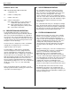
Supra-Blast Cartridge Dust Collector Revised 02/02 1. IMPORTANT NOTICE This manual contains important safety information and precautionary measures. It is impossible to list all potential hazards associated with every dust collection system in each application. Proper use of the equipment must be discussed with United Air Specialists, Inc. (UAS) or your local DUST-HOG® representative. Operating personnel must be aware of, and adhere to, the most stringent safety procedures.
Revised 02/02 EXAMPLE: SBD 24-3-H55 SBD – DUST-HOG Supra-Blast double-filter configuration unit 24 – number of cartridge filters 3– number of filter tiers H55 – unit base arrangement H55 - hopper with 44" (112 cm) clearance for standard 55 gallon (208 liter) drum SD - hopper with 26" (66 cm) clearance for UAS-supplied 30 gallon (114 liter) drum OB - open bottom construction 2.
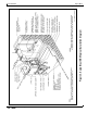
Supra-Blast Cartridge Dust Collector Figure 1. Supra-Blast Air Filter Operation & Cleaning 44-10001-0001 Revised 02/02 United Air Specialists, Inc.
Supra-Blast Cartridge Dust Collector Revised 02/02 3.
Supra-Blast Cartridge Dust Collector Figure 2. Supra-Blast SBS Typical Installation Diagram 44-10044-0001, REV A Revised 02/02 United Air Specialists, Inc.
Supra-Blast Cartridge Dust Collector Figure 3. Supra-Blast SBD Typical Installation Diagram 44-10003-0001, REV A Revised 02/02 6 United Air Specialists, Inc.
Supra-Blast Cartridge Dust Collector Figure 4. Recommended Unit Clearances 44-10007-0001 Revised 02/02 United Air Specialists, Inc.
Supra-Blast Cartridge Dust Collector Revised 02/02 In the case of spark producing processes, system design should incorporate measures to prevent live sparks from entering the dust collector. Consult local authorities for the location of this unit and any additional precautions to consider when collecting combustible, explosive or hazardous dusts. General warnings and cautions are provided in Section 1.1. The Supra-Blast dust collector should be mounted on a solid, level, reinforced concrete foundation.
Figure 5. Leg Assembly Details FIELD_INSTALL_DWG1/ SUPRABLAST/SALES/ FIELD_INSTALL_DRW/ SHEET 1 Revised 02/02 Supra-Blast Cartridge Dust Collector United Air Specialists, Inc.
Figure 6. Leg Brace Assembly Details FIELD_INSTALL_DWG1/ SUPRABLAST/SALES/ FIELD_INSTALL_DRW/ SHEET 2 Revised 02/02 10 Supra-Blast Cartridge Dust Collector United Air Specialists, Inc.
Supra-Blast Cartridge Dust Collector Revised 02/02 NOTE: Each hopper assembly is equipped with four 1/2" (13 mm) pry locations — two holes on front flange and two holes on rear flange. Refer to Figure 8, Detail K, to aid in aligning the hopper flange with the module flange. With filter module still supported, use hardware (refer to Figure 8, Section P-P) to bolt the hopper and filter module together. Securely tighten all hardware at the filter module and hopper.
Supra-Blast Cartridge Dust Collector Revised 02/02 with the hardware provided. Secure leg assemblies to the concrete mounting pad with appropriate anchoring hardware. 4.4 ELECTRICAL INSTALLATION ! C AU T I O N All electrical work should be performed by a qualified electrician in accordance with local electrical codes. Disconnect electrical power before installing or servicing any electrical component. ! C AU T I O N Avoid mounting the Supra-Clean, Supra-View or Supra-I.Q.
United Air Specialists, Inc. Figure 7.
14 FIELD_INSTALL_DWG1/SUPRABLAST/SALES/FIELD_INSTALL_DRW/SHEET 4 Figure 8. Module to Hopper Assembly Details Revised 02/02 Supra-Blast Cartridge Dust Collector United Air Specialists, Inc.
United Air Specialists, Inc. Figure 9.
Supra-Blast Cartridge Dust Collector Figure 10. Top-Mount Blower Support Leg Assembly 44-10064-0001 Revised 02/02 16 United Air Specialists, Inc.
Figure 11. Power and Elementary Wiring for Units with Supra-Clean Timerboard and Magnehelic/Photohelic Control 44-10209-0001 04-2552, REV E Revised 02/02 Supra-Blast Cartridge Dust Collector United Air Specialists, Inc.
Figure 12. Power and Elementary Wiring for Units with Supra-View Panel 44-10208-0002 04-2587 Revised 02/02 18 Supra-Blast Cartridge Dust Collector United Air Specialists, Inc.
United Air Specialists, Inc. Figure 13. Power and Elementary Wiring for Units with Supra-I.Q.
Supra-Blast Cartridge Dust Collector Figure 14. Solenoid Wiring to Pulse Controls 61-10004-0001 04-2554, REV C Revised 02/02 20 United Air Specialists, Inc.
Supra-Blast Cartridge Dust Collector Revised 02/02 multiple module solenoid valve enclosures with heaters are installed, daisy chain the wiring so that each heater will have 100/115/VAC, 50/60 Hz at all times. Make certain enough current is available to supply all heaters. Example: If three solenoid valve enclosures are supplied with cartridge heaters, make certain the voltage supply can deliver 3 amps (1 amp per heater). 4.
Supra-Blast Cartridge Dust Collector Figure 15. Pneumatic Valve Assembly 44-10042-0001 Revised 02/02 22 United Air Specialists, Inc.
Supra-Blast Cartridge Dust Collector Figure 16. Abrasive Inlet Installation 44-10045-0001 Revised 02/02 United Air Specialists, Inc.
Supra-Blast Cartridge Dust Collector Revised 02/02 ! C AU T I O N The silencer will require a separate support. Do not use the blower damper or outlet flange to support the silencer. Apply silicone around the bolt holes of the connecting flanges, lift the silencer into position and secure with the hardware provided. Install permanent supports (customer-supplied) and tighten all hardware before removing the lifting device.
Supra-Blast Cartridge Dust Collector Revised 02/02 If a drum lid latch kit was ordered, attach the separate clamp band around the 55-gallon (208 liter) drum or 30-gallon (114 liter) short drum, leaving the cinch bolt loose. Position the three latch pawls onto the drum lid catches, rotating the drum lid as required. Tighten the cinch bolt and adjust the latch tension or band placement as required (refer to Figure 17).
Supra-Blast Cartridge Dust Collector Figure 18. Supra-Blast Typical Pressure Gauge Installation 44-10043-0001, REV A Revised 02/02 26 United Air Specialists, Inc.
Supra-Blast Cartridge Dust Collector Revised 02/02 supply interconnecting signal cord and mounting hardware for remote blower start/stop assembly installation. Remove jumper between terminals L and 20 in the combination magnetic motor/blower starter control package as shown in Figure 11, 12 or 13. 5. OPERATION ! C AU T I O N Shut off unit disconnect and lock out all electrical power to the dust collector prior to performing service work.
Supra-Blast Cartridge Dust Collector Revised 02/02 Check the differential pressure reading across the dust collector clean to dirty air sections. A normal differential pressure drop reading is between 1"-6" w.g. (25-152 mmAq). At start-up, this reading is generally in the 1"-3" w.g. (25-76 mmAq) range. Please list the reading here for future reference. Initial dust collector differential pressure reading across filters is ___________ " w.g. or ___________(mmAq) on ___________ (date).
Supra-Blast Cartridge Dust Collector Revised 02/02 PHOTOHELIC GUAGE CONTROL WITH SUPRA-CLEAN TIMERBOARD When using a Photohelic Guage with Supra-Clean timerboard, the timerboard is set to “PS” pulse mode (pulse cleaning activated by the Photohelic control) or “Continuous Clean” pulse mode to override the Photohelic Guage. With the Photohelic Guage control, the desired pressure can be maintained by adjusting the high and low setpoints on the gauge.
Figure 19. QuickSeal Filter Access Door and Supra-Max Series Filter Installation 44-10006-0001 Revised 02/02 30 Supra-Blast Cartridge Dust Collector United Air Specialists, Inc.
Supra-Blast Cartridge Dust Collector Revised 02/02 TO REPLACE CARTRIDGE FILTERS (refer to Figure 19): 1. Read and follow caution instructions in Section 6 before servicing dust collector. Start with the top row of QuickSeal doors. 2. Tap the metal surface of each door cover to remove collected particles from the inner door gasket. Pull the QuickSeal door handle away from the dust collector until the handle makes a 90° angle with the door cover. The door assembly is now in an unlatched position.
Supra-Blast Cartridge Dust Collector Revised 02/02 gate, close the slide gate before servicing the dust storage drum(s). The dust collector fan and compressed air cleaning systems do not have to be turned off if the hopper slide gate is closed prior to servicing storage drums. Remember to open the slide gate when the dust storage drum is replaced. 6.
Supra-Blast Cartridge Dust Collector Revised 02/02 7. TROUBLESHOOTING GUIDE Use the troubleshooting guide to correct any problems that occur with your dust collection unit. If the problem or condition continues, contact the nearest UAS customer service office listed on the back cover of this manual. ! PROBLEM Motor/blower won’t start or won’t stay running. Dust emissions from clean air discharge.
Supra-Blast Cartridge Dust Collector Revised 02/02 7. TROUBLESHOOTING GUIDE (CONTINUED) PROBLEM Continual, excessive pressure drop (over 7" [178 mm]) on filter monitoring gauge. POSSIBLE CAUSES RECOMMENDED SOLUTIONS Compressed air supply problems. Check incoming compressed air for proper supply at air manifold reservoir (90-110 PSIG [6.4-7.2 BAR]), pulse flow (2.2 cubic feet [62 liters] per pulse) and pulse duration (100 milliseconds). Correct any problems.
Supra-Blast Cartridge Dust Collector Revised 02/02 8. ILLUSTRATED PARTS 44-10009-0001 ® DUST-HOG Supra-Blast Series United Air Specialists, Inc.
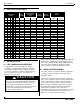
Supra-Blast Cartridge Dust Collector Revised 02/02 Supra-Blast Series Dust Collector Bill of Materials Item 1 2 2a 2b 2c 2d 2e 2f 2g 3 3a 4 5 5a 6 7 7a 8 8a 9 9a 9a 9b 9c 9d 9e 10 11 12 13 14 15 16 17 18 18a 18b 18c 18d 19 36 Part No. Description 33-10001-XXXX 02-10019-0001 42-10002-0001 42-10005-0001 Supra-Max Series Cartridge Filter (refer to Section 6.
UNITED AIR SPECIALISTS, INC. LIMITED WARRANTY UAS warrants all equipment manufactured and sold by UAS against defective parts and workmanship for one year from date of shipment to Purchaser. This warranty is subject to the limitations in UAS’ standard terms and conditions provided to Purchaser. Any unauthorized repairs or modifications or abnormal use or misuse of equipment will void all warranties. In no case will UAS’ responsibility or warranty extend to equipment not manufactured by UAS.
To Order Genuine Supra-Blast Replacement Parts and Supra-Max Series Replacement Filters, Contact the Nearest United Air Specialists Office. United Air Specialists, Inc. 4440 Creek Road, Cincinnati, Ohio 45242 USA Tel: National 1-800-252-4647 Tel: National 1-513-891-0400 Fax: 1-513-891-4882 United Air Specialists (U.K.