
User's Manual


Connector P2 CHAPTER 1 - M1020 EVALUATION MODULE
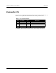
D1120 EVALUATION KIT QUICK START GUIDE 3
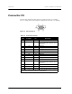
Connector P2
Connector P2 is an HD-15 female connector, as shown in Figure 1-2. It assumes
0 to 1.5 V analog inputs, and is unfiltered. All digital I/O are LVTTL (3 V) signaling.
Figure 1-2. HD-15 Female Connector
cWarning: Reverse biasing these inputs may result in damage to the device.
Table 1-2. P2 Connector Pinouts
Pin
Number
Pin Name I/O Description
1TX OUART Transmit
2 D5 I/O Digital I/O 5 or SOF
(see the M1020 Mote Integration Guide,
Appendix C)
3 D2 I/O Digital I/O 2
4 A7 I Analog input 7
5 A4 I Analog input 4
6 RX I UART Receive
7 D6 I/O Digital I/O 6
8 D3 I/O Digital I/O 3
9 GND I Ground
10 A5 I Analog input 5
11 D7 I/O Digital I/O 7
12 D4 I/O Digital I/O 4 or CTS
(see the M1020 Mote Integration Guide,
Appendix C)
13 D1 I/O Digital I/O 1
14 A6 I Analog input 6
15 A3 I Analog input 3
Note: All I/O, including UART, are at LVTTL (3 V) signaling levels. An external
level converter is required for RS-232 communications.