
User's Manual


4 Dust Networks ETERNA2 Regulatory User Guide
1 Introduction
1.1 Purpose
This document is provided to OEMs for the installation of the ETERNA2 into a finished product. Provided the OEM’s usage
of ETERNA2 is compliant with the requirements included in Section 6, the OEM is not required to complete radio
certification of ETERNA2’s radio performance in FCC, IC and CE regulated geographies. In addition this manual provides
the information necessary to perform certification of the ETERNA2 module for other geographies.
1.2 Scope
This document is intended for those who are responsible for installing and testing the ETERNA2 module design for
regulatory requirements.
1.3 References
[1] IEEE Std 802.15.4-2006, Wireless Medium Access Control (MAC) and Physical Layer (PHY) Specifications for
Low-Rate Wireless Personal Area Networks (LR-WPANs)
1.4 Definitions
DUT Device Under Test
Mote A node in a mesh network
Low Channel The lowest frequency channel occupied by ETERNA2 is channel 0 centered at 2405 MHz.
This channel corresponds to channel 11, as defined by [1].
Mid Channel The channel closest to the center of the 2.4 GHz ISM band occupied by ETERNA2 is channel
7, centered at 2440 MHz. This channel corresponds to channel 18, as defined by [1].
High Channel The highest frequency channel occupied by ETERNA2 is channel 14, centered at 2475 MHz.
This channel corresponds to channel 25, as defined by [1].
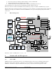
1.5 General Description
ETERNA2 combines a microprocessor and a IEEE-802.15.4 radio with networking capabilities to provide a time
synchronized, ultra low power network, designed to enable operation from battery sources for extended periods of time. The
design is a PCB including “castellated” leads for access to the device and network, an SoC (includes radio and CPU), power
supply filtering, and an MMCX connector to the antenna port or integral antenna.
1.6 Operational Description
ETERNA2 provides a IEEE 802.15.4 compliant radios that modulate a DSSS OQPSK set of symbols at a chip rate of 2
Mcps. Dust radios operate on a TDMA time schedule that uses either 7.25 or 10 ms timeslots. A transmit timeslot consists of
5 stages:
1. Initialization: radio is prepared for transmit (transmitter is off)
2. Ramp: transmitter is ramped to peak power
3. Transmit: 128 bytes of data maximum + 5 bytes preamble/SFD
4. Turnaround: radio is set to receive
5. Receive: radio waits in receive for ACK, then turns off
Total transmit time for a 128 byte packet plus all overhead (SFD / Preamble / Ramp) is 4.33ms.
A receive timeslot consists of 5 stages:
1. Initialization: radio is prepared for receive
2. Check for start of packet – if no packet is received within a guard time the radio is disabled and no further action is
taken