
User's Manual


ETERNA2 Regulatory User Guide Dust Networks 5
3. Receive the packet: up to 128 bytes of data maximum + 5 bytes preamble/SFD
4. Turnaround: radio waits 1 ms and then is set to transmit
5. Transmit: radio sends an ACK (21 bytes of data + 5 bytes preamble/SFD), then turns off
Total transmit time for an ACK is plus all overhead (SFD / Preamble / Ramp) is 1.101 ms.
Measured records and calculations of ETERNA2 radio transmit duty cycling are included in “ETERNA Duty cycle.pdf”.
When the radio is not in operation, the CPU is occasionally (every few seconds for a few milliseconds) operating, monitoring
temperature and voltage. The remainder of the time the ETERNA2 in a low power mode operating solely from a 32 kHz
crystal source.
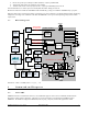
1.7 Block Diagram
Cortex-M3
Timers
Sched.
Auto
MAC
AES
Flash
512 KB
Flash
Controller
802.15.4
Framing
DMA
802.15.4
Mod
802.15.4
Demod
API
UART
(6-pin)
IPCS
SPI
Slave
PTAT
PMU /
Clock
Control
Bat.
Load
SRAM
72 KB
Code
System
LNA
PA
BPF PPF
PLL
RSSI
LPF
20 MHz
Analog Regulator
Clock Regulator
Core Regulator
Voltage Reference
Primary
DC/DC
Converter
PA
Regulator
PoR
32 kHz
ADC
Ctrl.
10-bit
ADC
Relaxation
Oscillator
32 kHz, 20 MHz
4-bit
DAC
VGA
CLI
UART
(2 pin)
LimitterADC
AGC
DAC
Microprocessor
Clock 1.8432 to
18.432 MHz
Rx VCO out = fc – 2.5 MHz
Tx VCO out = fc MHz
Timer Clocks
32.768 kHz &
20 MHz
Note that fc = 2405 + n*5 MHz, where n = 0, 1, 2, … 14.
2 Command and Response
2.1 CLI UART
ETERNA2 includes a Command Line Interface, CLI, UART that supports a full set of text commands described in this
document to enable product certification. The interface operates at LVTTL levels matching the VSUPPLY input to
ETERNA2. The UART is configured at 9600 baud, 8-bit, no parity, 1 stop bit, and does not support flow control.