
User's Manual


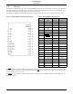
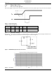


Table Of Contents
- 1.0 Absolute Maximum Ratings
- 2.0 Normal Operating Conditions
- 3.0 Electrical Specifications
- 4.0 Radio
- 5.0 Pinout
- 6.0 Mote Boot Up
- 7.0 Interfaces
- 7.1 Timestamps
- 7.2 Status
- 7.3 Serial Interface
- 7.3.1 Serial Handshake Protocol
- 7.3.2 Mote Command Data Types
- 7.3.3 Mote Commands
- 7.3.3.1 Command 0x80 Serial Payload Sent to Mote Serial
- 7.3.3.2 Command 0x81 Unacknowledged Serial Payload Received from Mote Serial
- 7.3.3.3 Command 0x82 Acknowledged Serial Payload Received from Mote Serial
- 7.3.3.4 Command 0x84 Time/State Packet
- 7.3.3.5 Commands 0x87 and 0x88 Set Parameter Request/Response
- 7.3.3.6 Commands 0x89 and 0x8A Get Parameter Request/Response
- 7.3.3.7 Command 0x8C Mote Information
- 7.3.3.8 Command 0x8D Reset Mote
- 7.3.4 Mote Get/Set Command Parameters
- 7.3.5 HDLC Packet Processing Examples
- 8.0 Packaging Description
- 9.0 Regulatory and Standards Compliance
- 10.0 Ordering Information

Interfaces
M2135-1/M2030-1 MOTE DATASHEET DUST NETWORKS™ 9
CONFIDENTIAL
6.3 Serial Interface Boot Up
Upon mote power up, the MT_CTS line is high (inactive). The mote serial interface boots within boot_delay (see Table 14) of
the mote powering up, at which time the mote will transmit an HDLC Mote Information packet, as described below in section
7.3.3.7. Note that full handshake (see 7.3.1.3) is in effect and is required to receive this packet.
7.0 Interfaces
7.1 Timestamps
The M2135-1/M2030-1 has the ability to deliver network-wide synchronized timestamps. The M2135-1/M2030-1 sends a
time packet (as described in
Table 42) through its serial interface when one of the following occurs:
• Mote receives an HDLC get_parameter request for time/state (see Table 41)
• Mote TIME signal is activated
The TIME pin is optional and has the advantage of being more accurate. The value of the timestamp is taken within
approximately a millisecond of receiving a
TIME signal activation. If the HDLC request is used, because of packet processing,
the value of the timestamp may be captured several milliseconds after receipt of the packet. The real time delivered to the
sensor processor is relative to the real time clock on the Manager which serves as the network real time clock (NRTC). The
time stamp skew across the network is guaranteed to be within ±250 ms of the NRTC.
Figure 6 Real Time
When the time pin is activated for at least min_strobe_length (see Table 14), the mote responds by sending the time packet
within 100 ms delay.
Figure 7 Operation of Time Pin
7.2 Status
The M2135-1/M2030-1 provides an output signal driving a status LED. This LED displays network connectivity information
and is used during mote installation. Alternatively, the mote’s network status may be polled via serial using the Get Parameter
command (see
7.3.3.6) with the mote state parameter (see 7.3.4.3).
Table 11 Status LED
LED Appearance Mote State
Off Off, or in sleep mode
Slow single blink (100 ms on, 900 ms off) On, and searching for potential network
Single blink (100 ms on, 400 ms off) On, and attempting to join network
Double blink (100 ms on, 100 ms off, 100 ms on, 700 ms off) On, connected to network, attempting to establish redundant
links
Solid on On, fully configured into network with redundant parents
PRELMINARY