User Guide Universal Presentation Switcher / Scaler DVI-3571a
TABLE OF CONTENTS SECTION PAGE PRODUCT SAFETY . . . . . . . . . . . . . . . . . . . . . . . . . . . . . . . . . . . . 1 PRODUCT LIABILITY. . . . . . . . . . . . . . . . . . . . . . . . . . . . . . . . . . . 1 1.0 INTRODUCTION. . . . . . . . . . . . . . . . . . . . . . . . . . . . . . . . . . . 2 2.0 SPECIFICATIONS. . . . . . . . . . . . . . . . . . . . . . . . . . . . . . . . . 3-4 3.0 PACKAGE CONTENTS. . . . . . . . . . . . . . . . . . . . . . . . . . . . . . 7 4.0 CONNECTING THE HARDWARE. . . . . .
WARNING – Product Safety 1. Do not dismantle the product housing or modify the printed circuit board module as this may result in electrical shock or burn. 2. Do not attempt to service this product yourself as opening or removing the product housing may expose you to dangerous voltages or other hazards. Refer all servicing to qualified service personnel. 3. Keep this product away from liquids. Spills into the product housing may result in fire, electrical shock, or equipment damage.
1.0 INTRODUCTION The DVI-3571a is a universal presentation switcher / scaler that is ideally suited for use in conference rooms, training facilities, classrooms, auditoriums, and other presentation applications. The DVI-3571a accepts up to eight (8) video inputs: 3x HDMI (or DVI), 3x RGB Analog (VGA), 1x Component Video and 1x Composite Video. Each input supports a broad range of signal formats and resolutions.
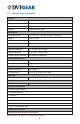
2.0 SPECIFICATIONS Performance Format Compliance HDMI v1.2, HDCP v1.1 and DVI v1.0 Video Input Formats Composite Video: NTSC or PAL Component Video: YPbPr / YCbCr HD15: Analog RGB,H,V HDMI: Digital RGB Maximum Pixel Clock Frequency 165 MHz Maximum Video Bit Rate 1.
2.1 Specifications (continued) Control Front Panel 13x Buttons with On-Screen Display navigation IR Remote Control IR Remote Control with On-Screen Display navigation RS-232 Serial communication, 9-pin Ethernet Web browser GUI or TelNet Mechanical Dimensions (H-W-D) 1.9” x 17.0” x 7.2” (47.0 mm x 432.0 mm x 183.0 mm) Weight 4.9 lbs. (2.
2.2 Supported Input Formats and Resolutions The DVI-3571a accepts HDMI or DVI (using DVI-to-HDMI adapter cable), HD15 (VGA), Composite Video and Analog Component Video via separate connectors. Each of the 8x input ports includes a dedicated analog stereo audio port.
2.3 Supported Output Formats and Resolutions The DVI-3571a has two HDMI or DVI (using DVI-to-HDMI adapter cable) outputs and one HD15 (VGA) output. The selected input signal is routed to all three outputs simultaneously. Auxiliary S/PDIF digital and stereo audio outputs are also included.
3.0 PACKAGE CONTENTS Before attempting to use this unit, please check the packaging and make certain the following items are contained in the shipping carton: • • • • • • • • 1x 1x 1x 1x 1x 4x 1x 1x DVI-3571a Universal Presentation Switcher / Scaler External AC Power Adapter User Guide IR Remote Control Unit IR Receiver Rubber Feet Rack-Mount Ears (set of 2) HD-15 to 3-RCA adapter cable Note: Please retain the original packing material in case you need to return the unit.
5e CV + L/R Audio Input: Connect to a composite video + L/R audio source. 6 Ethernet Control Port: See Section 5.7 for details on Web GUI. 7 Master Power Switch: Turn device ON/OFF. Front panel power button is used to toggle standby mode. 8 DC Power Input: Locking female connector for AC Power Adapter. Note 1: For component video output, use the included HD15 to 3-RCA adapter cable. See table on page 6 for information on supported output resolutions.
5.0 OPERATING THE UNIT The DVI-3571a can be operated from either the front panel controls, the supplied Infrared Remote Control, the RS-232 port or the Ethernet port. Please take the time to familiarize yourself with the location and function of the various control buttons on the Controller. 5.
5.2 Front Panel Controls The front panel has controls to manually control the DVI-3571a Universal Presentation Switcher / Scaler. 1 2 3 4 5 6 1 Power ON / OFF Button and LED: Turns unit ON or sets it to Standby (LED indicates status). 2 Infrared Receiver: Use with supplied IR remote. 3 INPUT Buttons and LEDs: Direct selection of source (LED indicates selected source). 4 MENU: Press to access OSD menus. 5 (− / +) Buttons: Press to navigate down / up in the OSD menu.
5.3.2 Menu Structure The OSD menu structure is as shown below. Items in bold and with an asterisk (*) are the factory default settings. Items in bold and in brackets [ ] are the default values for those settings.
The selection of the Video Menu or PC Menu is made automatically based on the selected input signal. Please note the differences in the menu structure to the left. The Display Menu allows user adjustment of several selections, such as output resolution, size (aspect ratio), info display mode, input HDCP mode, and several PC mode adjustments. The Output Function allows you to specify the output resolution you want the Switcher / Scaler to produce.
The PC Function is available when a PC input is selected. Several user adjustments are available. The Color Menu allows user selection of several image adjustments, such as contrast, brightness, color, hue, saturation, sharpness and noise reduction. The Color Function allows user adjustment of gain and offset. The RGB values are used to set the color balance of the white point, and the RGB Offset values are used to set the color balance of the black point of the image.
If an input video signal is not present, a solid color, called the Freerun Color, will be displayed. The Freerun Color Function allows user selection of either blue or black. The Information Menu contains technical information. If you have problems with the Switcher / Scaler and require assistance, a technician may ask you to read information from this menu as part of the troubleshooting process. 5.4 RS-232 Protocol The DVI-3571a is equipped with an RS-232 serial control port.
unit is set to Static IP Mode, then the factory default IP address is 192.168.0.1. To use the Telnet software on Windows XP, Vista, 7, or 8, follow the steps listed below: Note: Windows XP and Vista come with Telnet software installed and activated. However, on later versions of Windows such as Windows 7 and 8, the built-in Telnet software must be manually activated. Activate it by turning on “Telnet Client” through the Control Panel, Programs and Features, Turn Windows Features on or off.
5.6.1 RS-232 and Telnet Command Set In order to be executed, these commands must be followed by a Carriage Return (CR) command. For some systems, a Line Feed (LF) command may also be required. None of the following commands are case sensitive. Command Description S POWER 0/1 0 = OFF R POWER Reports the numeric equivalent for POWER setting (as above).
5.6.1 RS-232 and Telnet Command Set (continued) Command Description S SATURATION 0~60 Sets the numerical equivalent for the SATURATION setting (0~60). R SATURATION Reports the numerical equivalent for the SATURATION setting. S SHARPNESS 0~30 Sets the numerical equivalent for the SHARPNESS setting (0~60). R SHARPNESS Reports the numerical equivalent for SHARPNESS setting.
5.7 Web GUI Control To access the Web GUI Control capability, first make certain that the DVI-3571a unit and the control system being used are both connected to an active network. The DVI-3571a may be connected to the network using the Ethernet port on the rear panel. Open a web browser on the controlling PC or laptop and enter the Switcher / Scaler’s IP address into the web address entry bar. By default, the unit is set to DHCP mode and will be assigned an IP address by the network.
6.0 TROUBLESHOOTING If this unit does not appear to be functioning, bypass the Switcher / Scaler by using a short set of cables to connect each source device directly to a known good destination device, then verify that a proper image and sound are present. If the signal is present under these conditions, make certain that power is present to the Switcher / Scaler unit. Check to be sure the AC power adapter is plugged into a working AC power outlet and into the rear of the Switcher / Scaler.
7.0 LIMITED WARRANTY LIMITED WARRANTY – Subject to the limitations stated below, DVIGear warrants that this product will be free from defects in materials and workmanship for a period of three (3) years from the date of purchase. Should the product, in DVIGear’s opinion, prove defective within the warranty period stated above, DVIGear, at its option, will repair or replace this product without charge. Any defective parts replaced become the property of DVIGear.
Your Digital Connectivity Experts Toll Free 888.463.9927 Phone 770.421.6699 Fax 770.234.4207 DVIGear, Inc. 1059 Triad Court, Suite 8 Marietta, Georgia 30062-2258 www.dvigear.com DVI-3571a-UG-01 / September.