User Guide DVI-7520 DVI-7525 HDMI HDBaseT Extender Set, 70m HDMI HDBaseT Extender Set, 100m
TABLE OF CONTENTS SECTION PAGE PRODUCT SAFETY . . . . . . . . . . . . . . . . . . . . . . . . . . . . . . . . . . . . 1 PRODUCT LIABILITY. . . . . . . . . . . . . . . . . . . . . . . . . . . . . . . . . . . 1 1.0 INTRODUCTION. . . . . . . . . . . . . . . . . . . . . . . . . . . . . . . . . . . 2 2.0 SPECIFICATIONS. . . . . . . . . . . . . . . . . . . . . . . . . . . . . . . . . 3-4 3.0 PACKAGE CONTENTS. . . . . . . . . . . . . . . . . . . . . . . . . . . . . . 5 4.0 CONNECTING THE HARDWARE. . . . . .
WARNING – Product Safety 1. Do not dismantle the product housing or modify the printed circuit board module as this may result in electrical shock or burn. 2. Do not attempt to service this product yourself as opening or removing the product housing may expose you to dangerous voltages or other hazards. Refer all servicing to qualified service personnel. 3. Keep this product away from liquids. Spills into the product housing may result in fire, electrical shock, or equipment damage.
1.0 INTRODUCTION DVIGear’s DVI-7520 and DVI-7525 utilize HDBaseT™ technology to provide a simple and cost-effective solution for extension of uncompressed HDMI or DVI, embedded audio, bidirectional IR, RS-232 and Ethernet (DVI-7525 only) using a single twisted pair CAT-X cable. These extenders support the full range of HDBaseT features, including: 5-play, support for 4K / 30p (UHD) resolution, bidirectional IR, POH (Power over HDBaseT) and long-range operation.
2.0 SPECIFICATIONS DVI-7520 Model Extender Set Transmitter Receiver DVI-7525 DVI-7520: HDBaseT HDMI Extender Set, 70m DVI-7520-Tx: HDBaseT HDMI Transmitter, 70m DVI-7520-Rx: HDBaseT HDMI Receiver, 70m DVI-7525: HDBaseT HDMI Extender Set, 100m DVI-7525-Tx: HDBaseT HDMI Transmitter, 100m DVI-7525-Rx: HDBaseT HDMI Receiver, 100m Performance Video Supports HDMI v1.4, HDCP, and CEC HDBaseT Class Type HDBaseT Class B HDBaseT Class A Audio Supports HDMI embedded audio: up to 7.
2.1 Specifications (Continued) DVI-7520 HDBaseT DVI-7525 Recommended: CAT6A S/FTP (550 MHz) AWG 23 Required: CAT5e or better Category Cable Type Compliant with TIA/EIA-568B termination standard up to 230 ft. (70 meters) @ up to 330 ft. (100 meters) @ 1920x1080 / 60p / 36-bit 1920x1080 / 60p / 36-bit Maximum Extension up to 130 ft. (40 meters) @ up to 230 ft.
3.
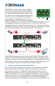
1 2 3 4 Transmitter Unit 1 2 3 4 5 6 7 8 2 3 Receiver Unit 5 6 7 8 6 7 8 Rear View 12 VDC Power Input: screw locking female connector for AC Power Adapter. HDBaseT Output: RJ-45 female connector. See warning below. IR IN: connect IR receiver to send IR signal over CAT-X cable to Rx Unit. IR OUT: connect IR transmitter to accept IR signal from Rx Unit and output to a source device. RS-232: 3-pin female phoenix connector for serial data pass-through.
DVI-7525-TX Control Laptop LAN (DVI-7525 only) 4K Upscaling Blu-Ray Player IR Tx 12 VDC Power Adapter HDBaseT CAT-X connection LAN (DVI-7525 only) DVI-7525-RX POH Remote Power 4K Projector IR Rx (remotely powered by transmitter) This HDBaseT extension system consists of a Transmitter unit (DVI-7520-TX or DVI-7525-TX) and a Receiver unit (DVI-7520-RX or DVI-7525-RX). To connect this system, first remove power from all devices (installing devices while powered may cause damage).
For RS-232, use serial cables and the supplied 3-pin phoenix connectors to connect a controller unit (e.g. touch panel) and serial controlled device (e.g. projector) to the RS‑232 ports on the Tx and Rx. Please see the drawing of the female phoenix connector on the unit for RS‑232 pin definitions. Tx Rx These extenders support bidirectional IR via two separate IR signals. An IR signal may be extended over the CAT-X cable from Tx Unit to the Rx Unit by doing the following.
For POH operation, connect the supplied AC Power Adapter to the 12 VDC Power Input on the transmitter unit and then to a working AC power source. Once the transmitter unit detects the POH compatible receiver unit, it will provide power over the CAT-X cable. If non-POH operation is desired, simply connect the optional AC Power Adapter to the 12 VDC Power Input on the receiver unit. In this case, the transmitter unit no longer supplies power to the receiver unit.
5.0 OPERATING THE UNIT Once all connections have been made and power has been applied to all components, this extension system should function immediately. This product has no adjustments and does not require configuration. 6.0 TROUBLESHOOTING WARNING: The HDBaseT ports are designed to connect to compatible DVIGear products only. Do not connect any device to the HDBaseT port of this product unless you are sure it is compatible. Connecting incompatible devices may cause harm to the devices.
7.0 LIMITED WARRANTY LIMITED WARRANTY – Subject to the limitations stated below, DVIGear warrants that this product will be free from defects in materials and workmanship for a period of three (3) years from the date of purchase. Should the product, in DVIGear’s opinion, prove defective within the warranty period stated above, DVIGear, at its option, will repair or replace this product without charge. Any defective parts replaced become the property of DVIGear.
Your Digital Connectivity Experts Toll Free 888.463.9927 Phone 770.421.6699 Fax 770.234.4207 DVIGear, Inc. 1059 Triad Court, Suite 8 Marietta, Georgia 30062-2258 www.dvigear.com DVI-7520_DVI-7525-UG-01 / August.