PC, DVI, VIDEO INTERFACE CONTROLLER FOR TFT PANEL Model: DVS-1600 Part number : 41714002X-3 INSTRUCTIONS CONTENTS Page: 2. Introduction, How to Proceed, Usage Note, Disclaimer 2. System design – Diagram of a suggested system 4. Assembly notes – Important information about system elements 6. Connection & Operation – How to use the controller 10. Connectors, pinouts & jumpers – Essential connection information 18. Controller dimensions 19. Application notes 21. Troubleshooting 22. Specifications 23.
Introduction Designed for LCD monitor and other flat panel display applications, the DVS-1600 controller provides easy to use interface controller for: ¾ ¾ TFT (active matrix) LCDs with LVDS / TTL single pixel interface of 1680x1050, 1600x1200, 1400x1050, 1440x900, 1366x768, 1280x1024, 1280x800, 1280x768, 1024x768, 1024x600, 800x600, 800x480, 640x480, 480x640 resolution Computer video signals of UXGA, SXGA, XGA, SVGA, VGA standard HOW TO PROCEED ¾ Ensure you have all parts & that they are correct, refer t
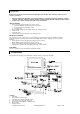
8. 9. 10. 11. 12. 13. 14. 15. 16. Function controls cable Backlight status Status LED 2 (Optional) Status LED 1 (Optional) ## IR sensor (Optional) Alternate Composite 1 / S-Video 1 input Analog VGA input / Composite 1 / S-Video 1 input DVI-D input Power input (12VDC / 24VDC) Digital View offers a range of accessories such as listed above, to make up complete display solution. ## - Support on V1.10.00 or up firmware revision. © Digital View Ltd 2010 www.digitalview.
ASSEMBLY NOTES This controller is designed for monitor and custom display projects using 1680x1050, 1600x1200, 1400x1050, 1440x900, 1366x768, 1280x1024, 1280x800, 1280x768, 1024x768, 1024x600, 800x600, 800x480, 640x480, 480x640 resolution TFT panels with a VGA, SVGA, WXGA, XGA, SXGA or UXGA signal input. The following provides some guidelines for installation and preparation of a finished display solution.
16. 12V / 24VDC power input : • Power Input: 12V DC / 24VDC is required, this should be a regulated supply. The power rating is depending on the panel and inverter used. Normally, power supply with 3.5Amp current output should enough for most of 4x CCFT panels. Although the controller provides power regulation for the LCD power this does not relate to the power supplied to the backlight inverter.
CONNECTION & OPERATION CAUTION: Never connect or disconnect parts of the display system when the system is powered up as this may cause serious damage. CONNECTION Connection and usage is quite straight forward (it is useful to have the relevant connection diagram available at this time): 1. LCD panel & Inverter: Connect the inverter (if it is not built-in the panel) to the CCFT lead connector of the LCD panel. 2. LVDS type panels: Plug the LVDS signal cable direct to CN1 (if necessary).
LCD DISPLAY SYSTEM SETTINGS NOTE: By way of explanation the following refers to a set of sample buttons that may be obtained as an option.
Select Auto video system detection Select PAL video system Select PAL M video system Select NTSC video system Select NTSC 4.43 video system Select SECAM video system Wide screen mode information display# Select the input mode (1280 / 1360 / 1366 / 1368) to recognize and display the correct input signal information display on the OSD menu.
Exit Exit the OSD menu and save the settings Autosetup Auto adjust the positions, phase, frequency Frequency Yes No Adjust the image horizontal size Phase Fine tune the data sampling position (adjust image quality) Image Horizontal Position Image Vertical Position Exit Use +/- to move the image horizontally Press – or + (Use +/- to move the image vertically Press – or + (Exit the OSD menu Position# +) +) Utilities OSD setting 4 Load Factory Default Sharpness Exit OSD Timeout : 0 / 10 / 20 / 30
CONNECTORS, PINOUTS & JUMPERS The various connectors are: Summary: Connectors Ref Purpose CN1 LVDS panel signal CN2 TTL panel signal CN8 Reserved CNA1 Auxiliary power output CNB1 Backlight inverter CNB2 Backlight status CNC1 Function controls CNV1 Alternate Composite 1 / S-Video 1 video in CNV2 Reserved CNV3 Reserved CNV4 Reserved ## IR1 Infra-Red sensor connector LED1 Dual color LED connector for controller status LED2 Dual color LED connector for backlight status P1 ARGB signal input P2 DVI-D signal inpu
Summary: Jumpers setting Ref Purpose JA1 On board +5V logic power enable JA3 Panel power voltage select JA6 Panel power voltage select JB1 Backlight brightness voltage range JB2 Backlight inverter on/off control – signal level JB3 Backlight inverter on/off control – polarity JB5 Backlight control type selection JB6 Backlight status JP1 Reserved JP2 JP3 JP6 Reserved Reserved Input power control JT1 JT2 Reserved Composite 1 video-in terminator enable JT3 S-Video 1 chroma-in terminator enabl
Input voltage via PP2 Panel Voltage JA3 JA6 3.3V 3V3 closed 1-3 & 2-4 5V 5V closed 1-3 & 2-4 12V 12V closed 3-5 & 4-6 18V 18V closed 3-5 & 4-6 Jumper on board 24VDC** CAUTION: Incorrect setting can damage panel & controller ** Please make sure the backlight inverter must support 24V supply. Because CNA1 pin 1 and CNB1 pin 2 will output 24VDC if input 24VDC via PP2.
DIP Switch selection – SW1 Pos #1 Pos #2 Pos #3 Pos.
Pos #5 OFF ON OFF ON OFF ON OFF ON Pos #6 OFF OFF ON ON OFF OFF ON ON Pos #7 OFF OFF OFF OFF ON ON ON ON Description WUXGA UXGA SXGA WXGA XGA SVGA VGA / WVGA Others SW1 Pos 8 = Reserved. DIP switch selection – SW2 Pos. # Function 1 Panel pixel format Description OFF : Double Pixel ON : Single Pixel 2 LVDS data mapping select ON : Mapping A (LVDS panel) OFF : Mapping B (LVDS panel) Please adjust to get the correct picture. See as Appendix II for details of mapping A and B.
CN1 – Panel connector: Hirose, DF13A-40DP-1.25DSA (Matching type : DF13-40DS-1.
27 28 29 30 31 32 33 34 35 36 37 38 39 40 41 42 43 44 45 46 47 48 49 50 NC NC BA0 BA1 BA2 BA3 BA4 BA5 BA6 BA7 GND GND VS CLK HS DE PWR VLCD VLCD VLCD NC VLCD12/18 VLCD12/18 VLCD12/18 No connection No connection Data bit B0 Data bit B1 Data bit B2 Data bit B3 Data bit B4 Data bit B5 Data bit B6 Data bit B7 Ground Ground Vertical sync Dot clock Horizontal sync Display enable Power down control signal (5v TTL) Panel power supply (3,3V/5V) (selected by JA3 & JA6) Panel power supply (3,3V/5V) (selected by JA3
3 Red LED pin (anode) LED2 – Backlight status LED connector: 3-pin header PIN 1 2 3 DESCRIPTION Green LED pin (anode) LED pin common (cathode) Red LED pin (anode) IR1 – Infra-Red sensor connector: JST B3B-XH-A (Matching type : XHP-3) – Support in V1.10.00 or up firmware revision.
CONTROLLER DIMENSIONS The maximum thickness of the controller is 21.6mm (measured from bottom of PCB to top of components, including any underside components & leads). We recommend clearances of: • 5mm from bottom of PCB - if mounting on a metal plate we also recommend a layer of suitable insulation material is added to the mounting plate surface. • 10mm above the components • 3~5mm around the edges Any of the holes shown above can be used for mounting the PCB, they are 3.2mm in diameter.
APPLICATION NOTES USING THE CONTROLLER WITHOUT BUTTONS ATTACHED This is very straightforward by following the steps below : • Firstly setup the controller/display system with the buttons. With controls attached and display system active make any settings for colour and image position as required then switch everything off. • Use a jumper to close JP6 jumper, this will fix the board On.
Design Guideline for making VR circuitry : Signal description / Notes : 1) R1 : 470ohm on board 2) RPOT is an external potentiometer (in-line dip style) that can be plugged directly into CNC1 pins 3,4,5. RPOT must be supplied / installed by user. 3) BVR_B : Voltage tapped from “top” of potentiometer, the node of R1 and RPOT. 4) BVR_WIP : Voltage tapped from wiper arm of RPOT. 5) BVR_A : Voltage tapped from “bottom” of RPOT. Note : BVR_A voltage is left floating on the controller board.
TROUBLESHOOTING General A general guide to troubleshooting a flat panel display system it is worth considering the system as separate elements, such as: ¾ Controller (jumpers, PC settings) ¾ Panel (controller, cabling, connection, panel, PC settings) ¾ Backlight (inverter, cabling, backlight tubes) ¾ Cabling ¾ Computer system (display settings, operating system) Through step by step cross checking with instruction manuals and a process of elimination to isolate the problem it is usually possible to clearly
SPECIFICATIONS Panel compatibility 1680x1050, 1600x1200, 1400x1050, 1440x900 1366x768, 1280x1024, 1280x800, 1280x768, 1024x768, 1024x600, 800x600, 800x480, 640x480, 480x640 TFT LVDS or TTL single pixel LCD’s support. No. of colours Up to 3 x 8 bit providing 16.7 million colours. Vertical refresh rate UXGA, SXGA, XGA, SVGA, VGA resolution up to 60Hz. Graphics formats Standard UXGA, SXGA, XGA,SVGA,VGA Video formats PAL, PAL M, NTSC, NTSC 4.
Appendix I – Graphic & Video Mode Support Table Mode Resolution E1_70 640x350 70Hz 640x400 70Hz 640x480 60Hz 640x480 60Hz 640x480 60Hz 800x600 56Hz 800x600 56Hz 800x600 56Hz 800x600 60Hz 800x600 60Hz 800x600 60Hz 1024x768 60Hz 1024x768 60Hz 1024x768 60Hz E2_70 V_60 V_60 V_60 SV_56 SV_56 SV_56 SV_60 SV_60 SV_60 X_60 X_60 X_60 SX_60 SX_60 SX_60 UX_60 UX_60 UX_60 1280x1024 60Hz 1280x1024 60Hz 1280x1024 60Hz 1600x1200 60Hz 1600x1200 60Hz 1600x1200 60Hz Clk [MHz] Horizontal Vertical Sync Mode freq [KHz] fr
COMPOSITE, S-VIDEO INPUT PORT : System Resolution Horizontal freq [KHz] Vertical freq [Hz] NTSC 720x480 15.7 60 NTSC 4.43 720x480 15.7 60 PAL 720x576 15.6 50 PAL M 720x576 15.6 60 SECAM 720x576 15.6 50 © Digital View Ltd 2010 www.digitalview.
Appendix II – RS-232 control protocols RS-232 Serial control (Baud rate 2400, 8 bits, 1 stop bit and no parity) Physical connection : Controller side Connector interface : CN8 Mating connector : JST XHP-6 6 5 PIN# 4 5 6 4 1 3 Computer side Connector interface : Serial port Mating connector : DB9 Female 1 Mating face of CN8 Description RS-232 Tx Data Ground RS-232 Rx Data 4 3 6 PIN# 2 3 5 7 8 5 9 Mating face of RS-232 DB9 Male Description RS-232 Rx Data RS-232 Tx Data Ground Remark : (1) : R
Image V position # Sharpness Frequency # OSD H position OSD V position Select menu timeout Input main select 0x87, nnnn | “+” | “-” | “?” 0x8a, nn | “+” | “-” |”r” | ”R” | “?” 0x8b, nnnn | “+” | “-“ | “?” 0x90, nnn | “+” | “-“ | “r” | “R” | “?” 0x91, nnn | “+” | “-“ | “r” | “R” | “?” 0x93, nn | “+” | “-“ | “r” | “R” | “?” Set img_vpos = value/increment/decrement Query Set sharpness= value/increment/decrement Reset Query Frequency = value/increment/decrement Query Set osd_hpos = value/increment/decre
Query Blue level for selected colour temperature Backlight brightness control 0xb6, nn | “+” | “-” | “r” | “R” | “?” 0xe0, nn | “+” | “-” | “r” | “R” | “?” Set the level of the blue channel for the selected colour temp. = value/increment/decrement Reset Query Set backlight brightness = value/increment/decrement Reset Query Blue level for selected colour temperature. Range: “8””0”-“F””F” Default: “F””F” Backlight brightness. Range: “0””0”-“F””F” Default: “F””F” e.
Hex to ASCII conversion table Hex 0x30 0x31 0x32 0x33 0x34 0x35 0x36 0x37 0x38 0x39 ASCII 0 1 2 3 4 5 6 7 8 9 Hex 0x41 0x42 0x43 0x44 0x45 0x46 0x47 0x48 0x49 0x4A 0x4B 0x4C 0x4D 0x4E 0x4F 0x50 0x51 0x52 0x53 0x54 0x55 0x56 0x57 0x58 0x59 0x5A © Digital View Ltd 2010 ASCII A B C D E F G H I J K L M N O P Q R S T U V W X Y Z Hex 0x61 0x62 0x63 0x64 0x65 0x66 0x67 0x68 0x69 0x6A 0x6B 0x6C 0x6D 0x6E 0x6F 0x70 0x71 0x72 0x73 0x74 0x75 0x76 0x77 0x78 0x79 0x7A www.digitalview.
Appendix III – Mapping definition • Definition of Mapping A : © Digital View Ltd 2010 www.digitalview.
• Definition of Mapping B : © Digital View Ltd 2010 www.digitalview.
Appendix IV – Auto Color Gain The Auto Color Gain function is supported in the ARGB mode only and is designed to calibrate the controller to the incoming video signal. In order to calibrate correctly, the display must be displaying an image containing both black and white data (see illustration below) when the function is used. The internal processor of the video controller chip will then execute a process to adjust the relative values of the RGB signals to achieve the best performance.
Appendix V – DV remote control unit work for DVS-1600 P/N 559000104-3 : DigitalView remote control unit (without DV logo silk screen printing) P/N 559000103-3 : DigitalView remote control unit (with DigitalView logo silk screen printing) BUTTON POWER BUTTON ATTENTION BUTTON** SEL UP ( ) / SEL DN ( ) + / - BUTTON DISPLAY BUTTON STOP (RGB) BUTTON TRACK (S-Vid) BUTTON TRACK (Comp) BUTTON FUNCTION Soft power ON/OFF button. Use combined with digit keys to enable/disable the IR function.
WARRANTY The products are warranted against defects in workmanship and material for a period of three (3) year from the date of purchase provided no modifications are made to it and it is operated under normal conditions and in compliance with the instruction manual. The warranty does not apply to: • Product that has been installed incorrectly, this specifically includes but is not limited to cases where electrical short circuit is caused.
CONTACT DETAILS USA: Digital View Inc. 18440 Technology Drive Building 130 Morgan Hill, CA 95037 USA Tel: (1) 408-782 7773 Fax: (1) 408-782 7883 Sales: ussales@digitalview.com EUROPE: Digital View Ltd 6 Marylebone Passage London W1W 8EX UK Tel: (44) (0)20 7631 2150 Sales: uksales@digitalview.com ASIA: Fax: (44) (0)20 7631 2156 Digital View Ltd th 16 floor Millennium City 3 370 Kwun Tong Road Kwun Tong Hong Kong Tel: (852) 2861 3615 Fax: (852) 2520 2987 Sales: hksales@digitalview.com WEBSITE www.