DVTEL INC. 65 Challenger Road Ridgefield Park, NJ 07660 Installation Manual trk-101 The contents of this guide may not be reproduced or reprinted in whole or in part without the express written permission of DVTEL, INC. Ver.
Installation Manual - sc1dn-A Table of Contents Document Information .........................................................................................................iv Introduction ......................................................................................................................... 1 2.1 Items Included in the Package ....................................................................................... 2 2.2 Hardware Description ................................................
Document Information List of Figures Figure 1: trk-101 Unit ................................................................................................................................. 1 Figure 2: trk-101 Unit Connectivity ............................................................................................................ 1 Figure 3: trk-101 Power Connection Panel ................................................................................................
Document Information Document Information Document Scope and Purpose The purpose of this document is to provide instructions and installation procedures for connecting the hardware equipment. This guide describes how to place and connect the trk-101 encoder in preparation for its setup and configuration. After completion of the hardware installation, additional setup and configurations are required before video analysis and detection can commence.
Document Information Disclaimer Users of DVTEL products accept full responsibility for ensuring the suitability and considering the role of the product detection capabilities and their limitation as they apply to their unique site requirements. DVTEL, Inc. and its agents make no guarantees or warranties to the suitability for the users’ intended use. DVTEL, Inc. accepts no responsibility for improper use or incomplete security and safety measures.
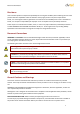
Document Information Warning: The unit cover is an essential part of the product. Do not open or remove this cover. Never operate the unit without the cover in place. Operating the unit without the cover in place poses a risk of fire and shock hazards. Warning: To prevent injury or damage to the unit, do not insert any objects into the vents of the unit. Warning: Only qualified trained personnel should service and repair this equipment.
Document Information Warning: Assure the connected electrical power source uses a circuit breaker or fuse no larger than 120 VAC, 15A or 240 VAC, 10A are used on the phase conductors (all current-carrying conductors). Caution: To avoid damage from overheating or unit failure, do not block the vents of the unit and assure, there is sufficient temperature regulation to support the unit’s requirements (cooling/heating). Ambient operating temperature should be kept in the range 0° to 50°C (32° to 122°F).
Document Information Site Preparation There are several requirements that should be properly addressed prior to installation at the site. The following specifications are requirements for proper installation and operation of the unit: Ambient Environment Conditions: Keep the unit in a clean and dry environment. Operating temperature should be maintained within 0° to 50°C (32° to 122°F). Operating humidity should be between 5% to 95% (non-condensing).
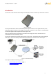
Installation Manual - sc1dn-A Introduction The trk-101 is a self-contained video analytic encoder that monitors the video input video from a camera. Figure 1: trk-101 Unit The unit provides alarms when it automatically detects specific events, such as region entrance, fence trespassing, tripwire crossover, which trigger an automatic notification. It also serves as a standard video encoder that digitizes and compresses the video input stream.
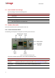
Introduction 2.1 Items Included in the Package The unit package contains the following items: QTY Description 1 trk-101 unit 1 Mounting bracket 1 Set of spring clamp terminal blocks 1 Set of documentation and utilities CD 2.2 Hardware Description This section describes the connection panels of the unit. 2.2.1 Power Connection Panel The following is a description of the power connection panel of the unit.
Introduction Item Description Alarm Input Single alarm input connection (a set of two wires) from an external device — for example, a fire sensor, PIR (passive infrared) sensor, fence sensor, etc. — with a dry contact output to the terminal block. Relay Output Dry output contact signal to a single external device (such as an electrical door lock) to the terminal block. The terminal is for Normally Open configuration.
Introduction 2.2.2 Video Connection Panel The following is a description of the video connection panel of the unit. Figure 4: trk-101 Video Connection Panel The video connection panel of the unit includes the following items: 4 Item Description Analog Video In (BNC) Input interface for receiving the surveillance camera analog video signal (source) for analysis and detection.
Installing and Connecting the Unit Installing and Connecting the Unit This section describes how to install and connect the unit and includes the following sections: Installing the Unit (page 5) Connecting the Unit (page 7) Resetting the Unit (page 12) Note: After connecting the unit, proceed to configure the unit as described in the HTML Edition Units User’s Guide. 3.1 Installing the Unit The unit can be installed and mounted next to the camera (inside the camera enclosure).
Installing and Connecting the Unit 3.1.1 Assembling the Unit in a Rack Mount Panel (Optional Accessory) Up to 10 units can be mounted on a single rack mount panel. After the units have been assembled in the rack mount panel, the panel can be installed in a standard 19-inch rack. To assemble units in a rack mount panel: 1. Remove the nut and washer from each of the two video connectors on the video connection panel of the unit. Figure 5: trk-101 with Nuts Removed 2.
Installing and Connecting the Unit 3. Fasten each unit using the nuts and washers removed in step 1, making sure to first place the washer on each video connector before tightening the nut on the video connector. 4. Repeat steps 1 through 3 for each of the units you want to assemble on the rack mount panel (up to 10 units can be assembled per panel). 5. Attach the rack mount panel to a 19" rack. 3.
Installing and Connecting the Unit To power to the unit using a power outlet: 1. Connect the AC adaptor output to the terminal block on the power connection panel of the unit. 2. Connect the AC adaptor to the power outlet. Warning: To prevent bodily injury or damage to the unit, use only properly rated and approved power supplies and/or AC adaptors. Warning: Make sure that the power supply matches the required specifications. Electrical safety should always be observed. 3.2.
Installing and Connecting the Unit To change the unit’s IP address: 1. Insert the CD included in the package in your computer’s disk drive. 2. Run the configurator.exe file by clicking on the icon. The Configurator application opens. 3. Select the unit by right-clicking on it. Figure 7: Configurator Window 4. In the Unit network configuration section, enter the IP address, Subnet mask, and Gateway IP address. Note: It is possible to set the IP address without changing the subnet. 5.
Installing and Connecting the Unit To connect a video source to the unit: 1. Securely connect the video cable connector (BNC) to the analog video output of the camera or video source. 2. Connect the other cable end (BNC) to the VIDEO IN connection on the video connection panel of the unit (see Figure 4: trk-101 Video Connection Panel). To set the video standard for the unit via its web interface: 1. Enter the IP address of the unit in a browser. The unit’s logon window opens. 2.
Installing and Connecting the Unit The analog Video Output (composite video) contains the video from the camera combined with On-Screen Display (OSD) overlays such as detected objects, tracking boxes and trails, time stamp, alarm, camera status, and so on. These OSDs can be enabled and customized using the unit embedded HTML user interface. The analog video output can be monitored using an analog monitor or recorded on a digital video recorder (DVR).
Installing and Connecting the Unit For more information on incident responses and relay outputs, refer to the HTML Edition Units User’s Guide. Warning: The signal from the Relay Output of the unit must be used as an indicator and not for direct control of a device. Caution: To prevent damage to the unit, do not exceed the voltage and current ratings for the relay terminals. Relay Contacts Schematics Figure 9: Relay Contacts Schematic The input supports opto-isolated signal for a single external device.
Installing and Connecting the Unit 3.3.1 Hard Reset Using the Reset Button The unit has a Reset button located on the power connection panel of the unit. (See Figure 3: trk-101 Power Connection Panel) To reset a unit using the Reset button: 7. Insert a small pointed object into the hole labeled Reset on the power connection panel of the unit. 8. Press in and release the button within 5 seconds. The unit resets to its last settings and the LED flashes green. 3.3.
Installation Manual - sc1dn-A Appendix The appendix contains the following sections: trk-101 Specifications (page 16) Connecting Leads to a Spring Clamp Terminal Block (page 18) Night Mode Max FPS (page 19) Troubleshooting (page 21) N/O to N/C Relay Configuration (page 23) 15
Appendix A.1. trk-101 Specifications The following are the trk-101 unit’s specifications: Video Input channels Number of Intelligent Video Analysis Channels 1 Analog Video Inputs Video Signal Composite 1Vp-p (PAL or NTSC) Physical Connector 1 x BNC 75Ω Analog Video Outputs Video Signal Composite 1Vp-p (PAL or NTSC) Physical Connector 1 x BNC 75Ω Digital Video Output IP video streaming Frame Rate (H.264) per Resolution H.
Appendix Environmental Specifications Operating Temperature 0° to 50°C (32° to 122°F) Operating Humidity 5% to 95% (non-condensing) Certifications Safety UL60950-1, CE, cTUVus Electromagnetic Interference (EMC) FCC Part 15, Subpart B, Class B; CE Class A; EN55022; EN55024; C-TICK Environmental RoHS 17
Appendix A.2. Connecting Leads to a Spring Clamp Terminal Block The unit is delivered with two terminal block connectors. The connectors enable you to connect wires for either the Relay Output or Alarm Inputs and then connect them to the unit. Figure 10: Spring Clamp Terminal Block To connect a wire to the spring clamp terminal block: 11. Strip the insulation form the end of each wire that is to be connected to the terminal block. Approximately 1 cm (2.54”) of wire should be exposed. 12.
Appendix A.3. Night Mode Max FPS A new setting, Night Mode Max FPS, has been added to the Setup>Camera>Video Settings>Advanced tab. This setting can be implemented via the camera’s web interface. Figure 12: Night Mode Max FPS Window This setting is used to improve the image quality in low-light situations by increasing the exposure time of the camera’s sensor, which, in turn, decreases the frames per second (FPS).
Appendix The actual encoder FPS will be the lower of the sensor FPS setting or the encoder FPS setting. The following table illustrates actual behavior of the FPS: Encoder FPS Setting Sensor FPS Setting Half (NTSC/PAL) Full (NTSC/PAL) (NTSC/PAL) Quarter (NTSC/PAL) 30/25 30/25 15/12.5 7.5/6.25 15/12.5 15/12.5 15/12.5 7.5/6.25 7.5/6.25 7.5/6.25 7.5/6.25 7.5/6.25 Actual Encoder FPS Note: When setting Quarter FPS, the system might not detect fast-moving objects.
Appendix A.4. Troubleshooting This section provides useful information and remedies for common situations where problems may be encountered. Problem Possible Solution No network connection Hardware issues: Check that the network is working and the unit is powered on. Check that the network (Ethernet) cable is properly attached to the unit. Confirm that the LED on the Ethernet (RJ-45) connector on the power connection panel of the unit is on.
Appendix Problem Bad output video quality Possible Solution Streaming video image is hanging (stopped) Alarm Inputs are not working Relay Outputs are not working 22 Check the source video signal quality by connecting an analog monitor to the video source. If video quality is acceptable, connect video source to the unit. Check that the cables are connected securely. This includes junction boxes and amplifier that may be used.
Appendix A.5. N/O to N/C Relay Configuration The on-board relay in the trk-101 provides a single contact which is by default Normally Open (N/O), enabling it to be configured to CLOSED upon an alarm condition. This is usually configured with a momentary closure (for example, five seconds), followed by returning to the OPEN condition, to be ready for the next alarm event.
Contacting DVTEL Contacting DVTEL To contact us, write us at info@dvtel.com, or contact your local office: CORPORATE HEADQUARTERS DVTEL, Inc. 65 Challenger Road Ridgefield Park, NJ 07660 USA Tel: 201.368.9700 Fax: 201.368.2615 Order Fax: 201.712.