
Installation manual


Installing and Connecting the Unit
7
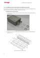
3. Fasten each unit using the nuts and washers removed in step 1, making sure to first place the
washer on each video connector before tightening the nut on the video connector.
4. Repeat steps 1 through 3 for each of the units you want to assemble on the rack mount panel
(up to 10 units can be assembled per panel).
5. Attach the rack mount panel to a 19" rack.
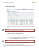
3.2 Connecting the Unit
This section describes the procedures for connecting the unit and includes the following sub-sections:
Grounding the Unit (page 7)
Connecting the Unit to the Power Supply (page 7)
Connecting the Unit to the Network (page 8)
Connecting the Video Source (Camera) to the Unit (page 9)
Connecting the Analog Video Output to an Analog Device (page 10)
Connecting the Unit to Receive Alarms from External Devices (Alarm Inputs) (page 11)
Connecting the Unit to Control an External Device (Using Relay Outputs) (page 11)
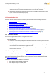
3.2.1 Grounding the Unit
The unit must be grounded according to local regulations and codes.
To ground the unit:
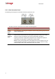
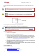
1. Loosen the screw of the grounding terminal located on the power connection panel of the unit.
(see Figure 3: trk-101 Power Connection Panel)
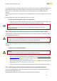
2. Attach a properly rated ground cable. Make sure the ring/spade terminal of the grounding
cable is between the toothed washers. Tighten the screw.
3. Ensure that the other end of the ground cable is connected to protective earth according to
local regulations and codes.
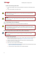
3.2.2 Connecting the Unit to the Power Supply
Before connecting to the power, please review the Electrical Safety Notice and Warnings (page vi).
Use a 12VDC/24VAC external power supply with suitable over current protection. Connect the power
supply wires to the positive and negative inputs on the terminal block connector labeled 12VDC/24VAC.
(See Power Connection Panel)
Following are the recommended AC adaptor specifications:
Power Adaptor Input: 110-240V, 47-63Hz, 1A
Power Adaptor Output: 12v DC 2A, 24W