
Installation & Assembly

dweLED.com
Phone (800) 526.2588
Fax (800) 526.2585
Headquarters/Eastern Distribution Center
4
4 Harbor Park Drive
Port Washington, NY 11050
Central Distribution Center
1600 Distribution Ct
LithiaSprings,GA30122
Western Distribution Center
1750 Archibald Ave
Ontario, CA 91761
dweLED retains the right to modify the des
ign of our products at any time as part of the company's continuous improvement program. Feb 2019 3
INSTALLATION INSTRUCTIONS
559 –LED Pendant
PD-55904/ PD-55906/ PD-55912
PREPARATION
1. Shut off the power at the circuit breaker and remove existing fixture, including the crossbar.
2. Carefully u
npack your new fixture and lay out all the parts on a clear area. Be careful not to lose any small parts
necessary for installation.
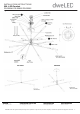
MOUNTING THE FIXTURE (Fig. 1)
3. Remove the mounting screw (B) from the fixture.
4. Secure back plate to the junction box using the screws provided with the junction box.
NOTE: The side of the mounting plate marked “GND” mus
t face out.
5. Choose number of rods suitable for your application. Thread the fixture wire through the rods, swivel and canopy.
Connect swivel, rods and fixture body. Make sure all are tightened.
6. Hook the safety cords to the back plate as shown (Fig. 1) (only PD-55912 need).
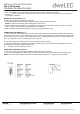
CONNECTING THE WIRES (Fig. 2)
7. Cut the extra wire. Connect the driver input wires
with junction box wires as shown (Fig.2). Make sure that all wire
connectors (A) are secure. If your outlet box has a green or bare copper ground wire, connect the fixture’s ground wire
to it. Otherwise, connect the fixture’s ground wire directly to the mounting plate using the green screw provided. After
wires are connected, tuck them carefully inside the junction box.
8. Place the fixture over the back plate and secure it with mounting screws (B).
9. Adjust the rotating joints to appropriate positions as shown (Fig. 1) (only PD-55912 and PD-55906 need), secure
joints with Allen screw (D) using Allen Wrench (C).
10. Thread the etched acrylic on the fixture.
COMPLETI
NG THE INSTALLATION
11. Secure the fixture to the mounting back plate using the mounting screws (B).
12. For slope ceiling application, rotate swivel at the top of the stem to ensure luminaires are aiming down (Fig.3).
NOTE: The fixture exceeds 28lbs, and must be installed using an outlet box U.L. approved for up to 100lbs.