TransVision 4 ™ TransVision™ 4 1.
Table of Contents Safety Instructions .......................................................................................... 2 Introduction ..................................................................................................... 5 Processor Front Panel Controls ..................................................................... 6 Processor Rear Panel—Connections and Installation.................................. 7 Programming URC-100 Remote Control to Operate TransVision™ 4 ........
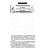
Safety Instructions WARNING HAZARDOUS VOLTAGE DO NOT OPEN ATTENTION COURANT ELECTRIQUE NE PAS OUYRIR ! CAN SHOCK, BURN OR CAUSE SEVERE INJURY OR DEATH. DO NOT REMOVE THE TOP COVER. REFER SERVICING TO QUALIFIED PERSONNEL. . 1. Read and apply all of the safety and operating instructions with your video equipment. 2. Keep all safety and operating instruction for future reference. 3. Unplug this video equipment from the wall outlet before cleaning. Never use liquid or aerosol cleaners.
the safety purpose of the polarized plug. 10. Route power supply cords so that they will not be walked on or pinched by items placed on or against them. Pay particular attention to cords at plugs, convenience receptacles, and the points where they exit the products. 11. Protect your video equipment from lightning during a storm or when it is left unattended and unused for long periods of time, unplug it from the wall outlet. This will prevent damage to the unit due to lightning and power-line surges. 12.
NOTE: This equipment is designed to operate in the USA, Canada and other countries where the broadcasting system and AC house current is exactly the same as in the USA and Canada. IMPORTANT INFORMATION FOR THE USER/FCC STATEMENT This equipment has been tested and found to comply with the limits for a Class B digital device, pursuant to Part 15 of the FCC Rules. The limits are designed to provide reasonable protection against harmful interference in a commercial environment.
Introduction TransVision™ 4 is a High Definition Digital Video Projection system comprising of two complementary components: a High Definition Video Projector featuring Dark Chip™ 2 Digital Light Processing (DLP™) technology from Texas Instruments and a Digital Video Processor. The TransVision™ 4 offers an outstanding progressive scan HDTV images with 16:9 aspect ratio and 1280 x 720 (720P) native resolution. The TransVision™ Projector may be floor or ceiling mounted and configured for front or rear projection.
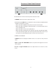
Processor Front Panel Controls The TransVision™ 4 Processor front panel controls include: • A POWER button to turn the system On or Off. • An indicator light (LED) which is lit when the unit is turned on and blinks when a valid IR command is received. — When the LED is DARK the AC power to the unit is turned off. — When the LED is flashing On and Off, power is connected and the unit is in the standby mode. — When the LED is on the unit is powered on.
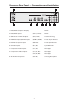
Processor Rear Panel — Connections and Installation 1 2 9 3 4 5 1. DVI/HDCP Output to Display 6 7 8 DVI-D 2. DVI/HDCP Inputs (DVI 1, DVI 2) DVI-D 3. Switched +12 VDC Outputs (RY1, RY2) 2.5mm DC Plug 4. RGBS Computer/HDTV Inputs (RGB1, RGB2) D-sub 15 pin Socket 5. RS-232 Computer Input (RS-232) D-sub 9 pin Socket 6. S-Video Inputs (S1, S2) 4 pin Mini-Din 7. Composite Video Inputs (V1, V2) RCA Type 8.
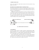
1. DIGITAL OUTPUT (DVI ) Connect the digital video output from the processor to the projector using DWIN’s DVI-D cable. Special Note about In-Wall Installations and Cable Lengths: A standard rectangular DVI connector is fairly large in size (approximately 2” wide) making it difficult to run through the walls. DWIN’s solution is to terminate one end of the DVI cable with a .75” circular connector that can easily run through a 1” conduit (figure 1).
The following are the pin assignments for the DVI-D connectors: Pin No. Signal Name Pin No. Signal Name Pin No. Signal Name 1 Data 2- 10 Data 1+ 18 Data 0+ 2 Data 2+ 11 Data 1 / Shield 19 Data 0 / Shield 3 Data 2 / Shield 14 +5V Power 22 Clock Shield 6 DDC Clock 15 Ground 23 Clock+ 7 DDC Data 16 Hot Plug Detect 24 Clock- 9 Data 1- 17 Data 0- 3. SWITCHED +12 VDC OUTPUTS The TransVision™ 4 Processor has two switched +12 VDC outlets (2.
7. COMPOSITE VIDEO INPUTS (V1, V2) The V1 and V2 inputs are provided for NTSC (480i) or PAL (580i) video sources, such as off-air tuners, satellite systems, cable boxes, VCR and DVD players. 8.
Programming URC-100 Remote Control to Operate the TransVision™ 4 Processor The TransVision™ 4 System is shipped with a factory pre-programmed remote control. 1.Press the TV device button. 2. Press and hold both the SHIFT and ENTER buttons for 3 seconds. The display will blink “Set” and then “DWIN.” 3.Enter the TransVision™ 4 brand code: 177 4.Press the LIGHT button on the right hand side to complete the programming. To operate other audio and video devices refer to the URC-100 Operating Manual.
Quick Reference Remote Control Operation DWIN AUD CD DVD AUX SAT TV VCR CBL OFF ON SHIFT PREV CH MUTE VOL CH TV VCR GUIDE INFO MENU EXIT = SELECT 1 2 3 4 5 6 7 8 9 +10 0 ENT MODE SUB CTR 12 REAR LIGHT
The remote control provided with the TransVision™ 4 is a universal remote control capable of controlling 8 different devices. 1. Select TV device to control the TransVision™ 4 System. 2. Press ON to turn the TransVision™ 4 ON. 3. Press OFF to turn the TransVision™ 4 OFF. 4. Press MENU to display the Main menu or to return to the previous menu. 5. Use the numbered buttons for direct switching of inputs. To select a specific input, press a numbered button.
Navigating the Control Menus Information Menu The Information menu reports the current status for input video source and lamp hours used. The Information menu may be accessed when no other menu is displayed on the screen. Information Input DVI 1 Format HD Video Type 720p Lamp Hours 58 1. To display the Information Menu, press INFO button on the remote control. 2. Press EXIT on the remote to clear the screen immediately.
Input Option All 10 video inputs may be selected either directly or through Input menu.
1. From the Main menu scroll up ▲ or down ▼ to highlight the Format option. This enables to select the aspect ratio. 2. Use the left ◀ or right ▶ buttons to sequentially select the aspect ratio. 3. Or use buttons 1-4 on the remote control for direct selection of Formats. 4. To change formats without entering the Main menu, Press the GUIDE button. To access the format option directly (bypassing the Main menu), press the GUIDE button followed by the corresponding number buttons: 1, 2, 3 or 4.
6. To restore the full Video menu , press MENU, up ▲ or down ▼ buttons. Picture setting changes made with the Video menu are saved in memory for each of the ten video inputs. Many video sources are different enough to require this fine-adjusting and these settings will be recalled each time a video input is selected. Setup Options 1. From the Main menu scroll up ▲or down▼ to highlight the Setup option. 2. Use the left◀, right ▶ or SEL buttons to advance to the Setup Options menu.
2. After adjusting to a desired menu position, press MENU button on the remote to go back to the Setup menu or press EXIT button to clear the screen. Num Buttons This feature selects between “Inputs” and “Power On” option. 1. When “Input” is selected, use the numbered buttons 0-9 for direct switching of inputs. 2. When “Power On” is selected, use the numbered buttons 0-9 to turn the power on and select the corresponding input.
Each input name can be of 11 characters long. 6. When you have completed renaming the first input, scroll left ◀ to exit the right column. 7. Scroll up ▲ or down ▼ the default list to repeat the process for all of the inputs you wish to rename. Rename Formats A default name is provided for each format such as Standard, Letterbox, Anamorphic, HD or Custom. To enter a different name, use the cursor to highlight Rename Formats and follow the same instructions as in the Rename Inputs menu.
Image Setup H-Position 230 H-Size 1280 V-Position 20 V-size 535 Special Note for DVI Inputs: DVI video signals contain image size and position information and generally do not require adjustments. Occasionally certain DVI input sources may contain extra lines or unwanted non-picture information, typically appearing as white horizontal lines along the top of the picture.
and right sides of picture to maintain the proper aspect ratio of the picture. For Custom Format Menu: 1. Scroll down to select ‘H-Size’ or ‘V-Size’. 2. Use the left ◀ or right ▶ buttons to set the desired image size. Custom Format H-size 1365 V-size 180 Relay Setup The Relay Setup allows you to assign the TransVision™ 4’s RY1 and RY2 screen trigger outputs to particular aspect ratio for to activate various accessories or controls in a home theater.
Projector Installation — Introduction Physical and electrical installation of the TransVision™ 4 must be performed only by a trained professional who is knowledgeable about both the specifics of the TransVision™ 4 and the requirements of the local building and electrical codes. Physical installation of the TransVision™ 4 may be divided into 3 steps: (1) Pre-installation planning, which includes plotting the projector-to-screen distance. This requires knowledge of the screen size and placement.
Projectors with fixed-pixel imaging arrays, such as DLP or LCD, are not recommended for use with perforated screens. Perforated screens have highly regular microscopic patterns that conflict with the equally uniform pattern in the digital image array. This creates interference, a visual artifact called a “moiré” pattern, which compromises picture quality. To eliminate light spill, a black felt border is also recommended to enhance the viewing experience. A2.
B. Mounting and Throw Distance Calculation Before starting the installation you will need to calculate the projector throw distance and the ceiling to top-of-picture offset. The throw distance and the precise center of the screen are then used to determine the exact location for the physical installation of the projector. �������������� � � ������ ������ � ������ The TransVision™’s zoom lens allows for a wide range of throw distance options — the distance from the projector to the screen.
For floor-mounted installations the picture offset is the distance between the mounting surface of the projector and the bottom of the picture. In order to deliver pictures that are free of keystone distortion, be certain to calculate the offset distance before ordering screens and/or cabinetry. Although some adjustment range is available in floor mounted systems by using the adjustable feet. (2) PREPARING FOR CEILING MOUNT INSTALLATION 2A.
2B. Ceiling Mount Preparation Once the throw distance has been calculated and the screen installed, the next step in the installation is to locate the precise mounting position of the projector. The ceiling mount bracket must be aligned to the middle of the screen and located as close as possible to an electrical source AND a support beam. If the projector is not located properly, it is not possible to compensate for any resulting “keystone” distortion in the projected image. IMPORTANT NOTES: 1.
2C. Ceiling Mount Installation and Projector Mounting The optional ceiling mount kit (CMB) consists of three parts. Before beginning the installation process, first identify each of the three parts of the mounting system as shown in the pictures below. NOTE: The ceiling must be capable of safely supporting the weight of the projector and mount, which is approximately 25 pounds. B2 C2 A2 B1 A1 Ceiling Bracket A C1 Ceiling Mount Kit Ceiling Bracket B Ceiling Assembly C Do Not Remove Hex Nuts! 1.
Ceiling Mount Kit Installation continued 4. Mount ceiling bracket “A” to the ceiling, making certain that the “FRONT” label faces the screen. 5. Place bracket “B” inside bracket “A” and then secure the two pieces together using the four hex head screws, making certain that the “FRONT” label faces the screen. 6. Turn the projector upside down and place ceiling assembly C over the bottom of the projector, with the “FRONT” label facing toward the lens.
2D. Connecting the TransVision™ 4 System LED A. Connect AC power receptacle to a non-switched 120 VAC outlet using the power cord provided with the TransVision™ 4 system. B. Connect the digital input to the TransVision™ 4 processor using the circular connector of DVI cable. NOTE: The TransVision™ 4 requires the use of a DWIN DVI cable between the Projector and the Digital Video Processor to operate correctly ! C. The IR Receiver and the Power LED are located on top of the projector. D.
(3) FINAL ADJUSTMENTS After the physical mounting is complete, horizontal and vertical adjustments can be made to center and align the projected image to the screen. Before making these adjustments you should: 1. Turn the system On. 2. Adjust the zoom and focus. Use the On-Screen Menus to help refine focus. 3. Once on screen menus can be clearly viewed, go to Screen Setup menu. 4. Make the following horizontal and vertical adjustments to align the white field pattern to the screen.
Physical Dimensions — TransVision™ 4 2.0” 4.5” 14 ” AC Input & Circular Connector 4.5” A 5.2” A “A” CEILING MOUNT HOLE LOCATION 13.5” 4.5” 4.50“ 11.0“ A A 2.50“ 4.50“ 7.10“ 12.
TransVision™ 4 RS-232 Control The RS-232 interface for the TransVision™ 4 System can be operated from any terminal, such as a Windows based PC running HyperTerminal. Communication Port Set-Up Connector pin-out Baud Rate: Parity: Stop bits: Num. of bits: Flow control: 9600 none 1 8 bits none 3 2 5 TX (Transmit Data) RX (Receive Data) GND (Signal Ground) Each command is enclosed in the [ ] character envelope. Note: Sequential commands must be separated with proper delays.
Projector Specifications Display Device 1280 x 720 DarkChip™ 2 DMD Number of Pixels 921,600 Screen Configuration Front or Rear throw Mounting Floor or Ceiling Zoom Range 1.26:1 Image Size 60 to 200 inch Diagonal Throw Distance 1.65 to 2.08 times Screen Width Projection Offset “Fixed” 14.4% of Picture Height + 4.
Digital Video Processor Specifications Video Systems HDTV / DTV / NTSC / PAL Scanning Formats 480i, 480p, 540p, 580i, 580p, 720p, 1080i PC Signals VGA / SVGA / XGA / SXGA INPUTS DVI 2 x DVI-D with HDCP Component 2 x RCA, Y: 1 Vp-p / 75 ohm Pb Pr: 0.7 Vp-p / 75 ohm S-Video 2 x 4 pin Mini-Din Y: 1 Vp-p / 75 ohm C: 0.
Lamp Replacement Procedure CAUTION! Take the following precautions to prevent electric shock, burns and injuries from broken glass. The projection lamp operates at very high pressures and temperatures. Some lamp failures may result in the projection lamp shattering. To prevent injuries from shattered glass, use caution when removing the lamp assembly from its housing.
Limited Warranty This warranty applies only to the first person or entity that purchases the TransVision™ 4 for personal or business use and not for the purpose of distribution or resale. The warranty period is for one (1) year from the date of purchase for labor and parts. DWIN Electronics shall not be liable or in any way responsible for any incidental or consequential damages of any kind.
• Unstable Pixel – No unstable pixels. DWIN Electronics will, at its option, either repair or replace the defect, or replace the defective product or part thereof at no charge to the owner for parts and labor covered by this warranty. If a unit is examined which is not in need of repair, you will be charged for the examination and return shipping. You must pay shipping charges incurred in getting your product to the factory. We will pay the return shipping charges if the repairs are covered by the warranty.
• any failed replacement lamp with a serial number that does not match the serial number of the replacement lamp. • damage occurring during shipment; • units which have been altered or modified in design, appearance or construction. To make a warranty claim on any lamp, you must contact DWIN Electronics and purchase a lamp using a credit card, check or money order: SERVICE DEPARTMENT DWIN Electronics, Inc. 710 North Mariposa St.