HDP-500 SUPERDATA PROJECTION MONITOR Installation and Operating Instructions Read these instructions completely before operating this unit. Contents subject to change without notice or obligation.
Table of Contents Safety Information ___________3 Important Information for the User___________________4 Specifications ___________5 Introduction ___________6 Pre Installation Preparations________________________7 Signal Connections___________________________________7 Front Panel Connections __________ ______8 Preparation for Adjustment___________________________9 Remote Control Operation __________10 Initial Set Up and Adjustment_______________________11 Focus Adjust Menu ________________11 Geometry Adjust
SAFETY INFORMATION 1. Read and apply all of the safety and operating instructions provided with your video equipment. 2. Keep all safety and operating instruction for future reference. 3. Unplug this video equipment from the wall outlet before cleaning. Never use liquid or aerosol cleaners. Use only a damp cloth for cleaning. 4. Do not use any attachments or accessories not recommended by the manufacturer as they may cause hazards. 5. Do not use this video equipment near water.
extensive work by a qualified technician to restore the video equipment to normal operation. e. If the video equipment has been dropped or the cabinet has been damaged. f. When the video equipment exhibits a distinct change in performance. 16.When replacement parts are required, be sure the service technician has used replacement parts specified by the manufacturer that have the same characteristics as the original part. Unauthorized substitutions may result in fire, electric shock, or other hazards. 17.
SPECIFICATIONS AND TECHNICAL DATA System Description: Red, Green, Blue three CRT/lens large screen refractive projection system for video and data applications. Separate screen required. Optics: USPL high resolution HD-145 data grade lenses. F1.03, hybrid design, fully color corrected. CRT’s: 7” Magnetic focus, liquid cooled with anti-reflective coated faceplate. 5.6” active raster diagonal and 70 degree deflection angle. Screen Size: 60 - 150 inch diagonal. Factory Preset for 100” diagonal.
This manual contains the information required to properly install, configure, setup and operate the DWIN HDP-500 data projection monitor. Please make certain that you fully read and understand the information in this manual before proceeding with any installation. THIS MANUAL CONTAINS IMPORTANT INSTRUCTIONS THAT WILL ASSURE A SAFE AND SUCCESSFUL INSTALLATION.
Planning a projection television installation is a critical part of the installation. Even with the extended range of mechanical and electronic correction circuitry built into the HDP-500, incorrect physical placement of the projector may place it outside the range of the circuits. Using the HDP-500 Projection software provided by DWIN, enter the width of the screen, the aspect ratio and the mounting position of the projector (ceiling, center of screen or floor).
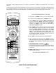
Make the appropriate connections to the front panel, using the following descriptions as a guide. 7 8 9 IR Input RS232C Input HDP-500 RED GREEN BLUE H/C SYNC DWIN V SYNC 120VAC 60Hz 1 2 3 4 5 6 1. Red Input: Connect the RED signal from the external decoder/processor to this jack. 2. Green Input: Connect the GREEN signal from the external decoder/processor to this jack. 3. Blue Input: Connect the BLUE signal from the external decoder/processor to this jack. 4.
Before initial adjustments are made to the unit, locate the correct distance from the screen. This distance should be obtained by using the HDP-500 Projection software supplied to you. Make certain that the front rubber feet are set so that the unit is level and parallel to the floor. You may wish to verify this with a standard carpenter’s level. In order to make certain adjustments, it is necessary to remove the unit’s cover.
The remote control supplied with the unit is factory programmed to operate the HDP-500 when “TV” mode is selected. SL-8000 remote furnished with the HDP-500 is a universal remote control capable of controlling 8 different devices. The operational instructions on this page refer to the remote buttons used with the HDP-500 only. Consult the SL8000 operating manual for complete information on programming the remote and using it with other devices. To control the HDP-500 select “TV” mode. 1.
At this point you are ready to proceed with the initial adjustment of the unit. Make certain that the power and signal connections have been made, and that a high quality signal feed is supplied from either a laser disc player or a test signal generator. NOTE: All initial adjustments will be saved in the Source memory with the preset name “LD-10”. If you wish to save the adjustments with a different name you must first create that name memory.
Press “1” to view the focus screen. Note that the screen will display the Focus menu against a background of the crosshatch/dot pattern. Signal Level Before adjusting focus you may wish to change the signal level for the on screen test pattern. This adjustment DOES NOT affect the actual signal level for picture displays, but it does allow lower signal levels during adjustments so that they are more precise. Low levels use less beam current.
Geometry Adjust Menu Geometry is the series of adjustments that correctly align the picture scans to the size of the screen. Just as important, geometry adjustments are used to compensate for the differences in alignment that result from the placement of the projector with regard to the screen. The HDP-500’s flexibility of geometry adjustments makes it possible to correct for differences caused by the projector’s “shooting angle” and mounting position as well as any tilt that may exist in the screen itself.
directly to the next step, or press “MENU” to exit. Center Pin 3.Center Pin 50 Look at the lines that intersect the center of the screen and use the / buttons on the remote to adjust the picture until they appear straight and perfectly level. It is often helpful to make these adjustments while standing at one side of the screen and looking inward toward the center of the picture. Use the / buttons on the remote to adjust the picture until the horizontal line that runs through the center of the screen.
Tilt 7. Tilt 50 At the Tilt screen, use the / and / buttons to adjust center horizontal and vertical lines parallel to the screen edges. When Tilt adjustments are complete, press “8” to move directly to the next step, or press “MENU” to exit. Horizontal Lines/Bottom Pin Cushion: 50 Adjust Horizontal & Vertical Center lines 8. Hor Lines/ Bottom Pin 50 This is another set of adjustments that set the picture so that it is perfectly parallel and evenly adjusted to the screen.
RED GEOMETRY The adjustments for Red Geometry are similar to those used to set the Green Geometry, except that instead of using the screen as a physical reference you will be matching the red channel to the green settings. The goal for all Red Geometry adjustments is to match the red lines on the test pattern directly over the green lines so that the result is a yellow line. 1. Center -Red Geometry1. Center 2. Size 3. Tilt 4. Key 5. Linearity 9. Green Geometry 0.
As with the Red Geometry, these adjustments will be to a master setting previously established. This time the blue will be adjusted to the green master channel. The adjustment procedure for blue is identical to that for red. Follow steps 1 to 5 above, except that this time you will be adjusting the blue, rather than red channel. Convergence Adjustments Once the picture has been focused and adjusted to the screen size for all geometry parameters, the next step in the set up process is convergence.
The coarse convergence is centered in nine areas around the edges of the raster and at the center of the image. The convergence is adjusted for a broad area around the center point. Convergence movement is intentionally slow in the course mode so that adjustments will be made with increased precision. In general, the coarse adjustment should be used first to establish a working start for the convergence process.
When all nine coarse convergence points have been converged press “2” to move to Fine Convergence. Fine Red Convergence Once the basic Coarse convergence is complete, press “2”, as noted above, to enter the Fine Red Convergence. Here the task is also to completely cover the green lines with the red so that there is no overlap. To start the procedure, use the / / / directional arrow buttons on the remote to move the solid wall cursor box to the upper left hand corner of the screen.
The next screen will instruct you to type the word “YES”. Do this using the up and down / arrow buttons on the remote as the letters change on the display. Use the left/right / arrow buttons to move the “typing” position to the next letter. When you have typed “YES”, press the “ENTER” button and the convergence memory will be emptied. You may now start the convergence process over from the factory settings.
Finally, set the Red and Blue gain controls so that the far right bar is as bright as possible while maintaining an even step of gray from one bar to the next across the screen. The far right bar should not be so bright that you cannot clearly distinguish eight separate bars on the screen. Press “1” and then use the / buttons to adjust the Red Gain and ”2” and / to adjust the Blue Gain. Note: The next two adjustments are available to consumers or end users even when the menu controls are protected.
To center the picture, press “MENU” to display the Main Menu, and then press “4” to access the Centering screen. When the Centering screen is displayed, use the / / / directional arrow buttons on the remote until the picture is properly centered both vertically and horizontally on the screen. If there is any overscan it should be equal the top/bottom and left/right edges of the screen.
To name the source, use the and arrow buttons on the remote to cycle through the alphanumeric characters. When the first character is set, use the button to move to the next position, and set the next character using the and arrow buttons. Again, when set, use the button to move to the next spot and the and arrow buttons to select the character. When the complete input name or designator is on screen, press “MENU” to enter the source name and settings to memory.
This will bring the highlight down to item 2, “Menu Access”, where “Enabled” is normally highlighted on the right side of the menu. This indicates that full access to all menus is allowed. To “Protect” the menus press the button, “Type the PASSWORD and then press ‘ENTER’ ”, message will appear at the top of the screen. A single cursor block will also appear at the right side of the “Menu Access” text line. You should now enter the password that will enable access to the menus.
• • • • High: This setting is roughly equivalent to a color temperature of 9,300° K . It will deliver the “brightest” picture at the expense of a slightly blue tint to black and white pictures. Normal: This is the factory default setting, and it is roughly equivalent to a color temperature of 6,500° . Low: This setting is roughly equivalent to a color temperature of 3,300° K. It will deliver the “warmest” picture at the expense of a slightly reddish tint to black and white pictures.
3. Open the top cover by removing the two screws located on the front bezel above either side of the center lens. Remove the top cover by holding it with one hand while pressing in on the metal tab at each side of the cover. Tilt the cover upward and pull it towards you ( away from the rear) to remove. 4. Change the H2 and V2 plugs on the Main Board by pulling them straight upwards and then rotate and reseat them as required so that the configuration matches the desired mode of operation. 5.
When the set is installed, you should explain the basic operational controls to the user: power on/off (using either the remote or automatic operation with source sensing), Source selection, brightness, contrast and center convergence adjustment, and the white balance and color temperature controls. You should also explain the functions of the LED indicator on the front panel of the HDP-500 as noted at the beginning of this manual.
When three channels have been focused, cover the blue lens with the lens cap and use the menu system to call up the Red Convergence pattern. You may reach this menu by pressing “Menu” to reach the Main Menu, “8” to reach the “Adjust” menu, “4” to reach the main “Convergence” menu and finally, “1” to reach the red convergence. To proceed with the alignment, loosen the two screws at the top of the red tube and the screw on the floor pan of the projector as shown in the diagram on this page.
Limited Warranty This warranty protects the owner of HDP-500 for one (1) year from the date of purchase for labor and parts. Implied warranties of merchant ability and fitness for particular purpose are limited in duration to a period of one year from the date of purchase. DWIN Electronics shall not be liable or in any way responsible for any incidental or consequential damages of any kind.
You must pay shipping charges incurred in getting your product to the factory. We will pay the return shipping charges if the repairs are covered by the warranty. Please save the original shipping cartons. A charge will be made for additional cartons. If your product needs service, you should notify us at: DWIN Electronics, Inc. 710 N. Mariposa St. Burbank, CA 91506 Tel.