
Specifications

M
ax Loop Resistance
F
or 4 to 20 mA Outputs
T
he maximum allowable loop resistance depends on the power supply voltage.
M
aximum loop voltage drop must not reduce the transmitter voltage below the 18
VDC minimum. Maximum loop resistance can be calculated with the following
equation. Vps is the power supply voltage.
R
max = Vps – 18
2
0 mA
S
ome receivers, particularly loop powered indicators, may maintain a fixed loop
voltage to power the device. This voltage drop must also be subtracted from the
power supply voltage when calculating the voltage margin for the transmitter. The
following equation takes this into account. Vrec is the receiver fixed voltage.
R
max = Vps – 18 – Vrec
2
0 mA
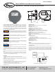
2 to 10 VDC Output
Before wiring for 2 to 10 VDC output, check that the jumper P1 is connected so that
the jumper is on the two pins closest to the terminal block as shown in figure 2. 2
t
o 10 VDC output may be powered by 18 to 28 VAC or VDC. The transmitter is
r
everse polarity protected. The load must be greater than 50 KΩ. The load and
p
ower supply should be connected according to Figure 2.
Figure 2
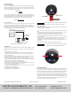
CALIBRATION
Calibration of the Model CMT200 requires an A-507A calibration adapter, model
GCK-200CO-2000CO2 calibration gas, a multimeter, and a small flat head screw
driver.
1. Turn off power to the transmitter.
2. Remove the lid from the housing by twisting it a quarter turn and pulling off.
3. Replace the receiver shown in figure 1 or 2 with a multimeter and restore the
power to the transmitter.
4. Attach the tubing from the zero calibration gas to the A-507A calibration adapter.
5. Securely attach the A-507A to the CMT200 as shown in figure 3.
6. Allow the calibration gas to flow at a rate of 0.5 to 1.0 slpm for at least 3 minutes.
7. Adjust the zero potentiometer (blue) until the output reading on the multimeter
reads 4 mA or 2VDC (depending on output selection).
8. Repeat steps 4 through 6 using the span calibration gas.
9. Adjust the span potentiometer (grey) until the output reading on the multimeter
reads 20 mA or 10 VDC (depending on output selection).
10. Turn off the power to the transmitter.
11. Replace the multimeter with the receiver as shown in figures 1 and 2 and
restore the power to the transmitter.
12. Remove the A-507A calibration adapter.
13. Replace the lid on to the transmitter.
F
igure 3
S
ensor Replacement
A
replacement sensor is available from Dwyer Instruments, Inc. Order part number
A
-505 for a replacement CO sensor.
1. Turn off power to the transmitter and remove the terminal block from the circuit
board.
2. Remove the two screws in the circuit board mounting bracket shown in Figure 4.
3
. Gently slide the circuit board and sensor out of the sensor guard.
4
. Remove sensor by gently pulling the sensor straight out of its sockets.
5
. Install the new sensor by gently pressing the pins of the sensor into the sockets
in the circuit board.
6. Slide the sensor and circuit board back into the sensor guard and align the
mounting holes on the circuit board brackets with the holes on the housing.
7. Reattach the circuit board bracket to the housing and the terminal block to the
circuit board.
8. Go through the calibration procedures in the calibration section.
Figure 4
MAINTENANCE/REPAIR
Upon final installation of the Model CMT200 Transmitter, no routine maintenance is
required with the exception of calibration. As with all electrochemical type gas
sensors, routine calibration is required. It is recommended the unit be re-calibrated
at 6 month intervals or as required by local ordinances or other requirements.
Except for sensor replacement and calibration, the Model CMT200 is not field
serviceable and should be returned if repair is needed (field repair should not be
attempted and may void warranty). Be sure to include a brief description of the
problem plus any relevant application notes. Contact customer service to receive a
return goods authorization number before shipping.
I
f the span potentiometer on the Model CMT200 cannot restore
the output to 20 mA, the sensor will need to be replaced.
When replacing the sensor, reset each potentiometer position
to the middle of the range before adjusting the calibration.
NOTICE
©Copyright 2013 Dwyer Instruments, Inc. Printed in U.S.A. 5/13 FR# 444080-00 Rev.1
DWYER INSTRUMENTS, INC.
Phone: 219/879-8000 www.dwyer-inst.com
P.O. BOX 373 • MICHIGAN CITY, INDIANA 46360, U.S.A. Fax: 219/872-9057 e-mail: info@dwyer-inst.com
P
1
P1
+
+
++
--
--
P
OWER
S
UPPLY
R
ECEIVER
P1 JUMPER SET
FOR CURRENT
VOLTAGE OUTPUT - WIRING AND P1 SETTING
SPAN
Z
ERO
3 2 1
NOTICE
Zero Adjustment
S
pan Adjustment