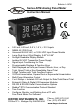
Bulletin: L-APM Series APM Analog Panel Meter Instruction Manual 0-20 mA, 4-20 mA, 0-5 V, 1-5 V, 10 V Inputs NEMA 4X, IP65 Front Universal 85-265 VAC, or 12/24 VDC Input Power Models Large Dual-Line 6-Digit Display, 0.60" & 0.
Analog Panel Meter Instruction Manual Disclaimer The information contained in this document is subject to change without notice. Dwyer Instruments, Inc. makes no representations or warranties with respect to the contents hereof; and specifically disclaims any implied warranties of merchantability or fitness for a particular purpose. ! CAUTION: Read complete instructions prior to installation and operation of the meter. WARNING: Risk of electric shock or personal injury.
Analog Panel Meter Instruction Manual Table of Contents INTRODUCTION ------------------------------------------------------------- 7 ORDERING INFORMATION ---------------------------------------------- 7 SPECIFICATIONS ----------------------------------------------------------- 8 General ------------------------------------------------------------------------------- 8 Process Input ---------------------------------------------------------------------- 9 Rate/Totalizer --------------------------------------
Analog Panel Meter Instruction Manual Setting the Input Signal (Input) ------------------------------------------ 36 Setting the Totalizer Features (total) ---------------------------------- 36 Setting the Input Units or Custom Tags (units)---------------------- 37 Setting the Decimal Point (dEc pt) -------------------------------------- 38 Programming the Rate/Totalizer (prog) -------------------------------- 38 Multi-Point Calibration & Scaling -------------------------------------- 39 Panel Meter Pro Sof
Analog Panel Meter Instruction Manual Scaling the 4-20 mA Analog Output (Aout) ---------------------------- 65 Reset Menu (reset) ------------------------------------------------------------ 66 Control Menu (Contrl) -------------------------------------------------------- 66 Setting Up the Password (pass) ------------------------------------------- 66 Protecting or Locking the Meter ------------------------------------------- 67 Total Reset Password & Non-Resettable Total ----------------------- 67 Making C
Analog Panel Meter Instruction Manual Table of Figures Figure 1: 1/8 DIN Panel Cutout and Mounting ................................... 16 Figure 2: Meter Dimensions - Side View............................................ 17 Figure 3: Meter Dimensions - Top View............................................. 17 Figure 4: Jumper Configuration for 12/24 VDC Power ..................... 18 Figure 5: Transmitter Supply Voltage Selection ...............................
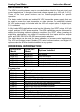
Analog Panel Meter Instruction Manual INTRODUCTION The APM is a multi-purpose, easy to use rate/totalizer ideal for flow rate, total, and control applications. It accepts current and voltage signals (e.g. 4-20 mA, 0-10 V). Three of the front panel buttons can be custom-programmed for specific operation. The basic model includes an isolated 24 VDC transmitter power supply that can be used to power the input transmitter or other devices.
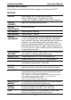
Analog Panel Meter Instruction Manual SPECIFICATIONS Except where noted all specifications apply to operation at +25°C. General DISPLAY Upper display: 0.6" (15 mm) high, red LEDs Second display: 0.46" (12 mm) high, red LEDs 6 digits: each (-99999 to 999999), with lead zero blanking.
Analog Panel Meter Instruction Manual ISOLATED Terminals P+ & P-: 24 VDC 10%. 12/24 VDC powered models TRANSMITTER selectable for 24, 10, or 5 VDC supply (internal jumper J4). POWER SUPPLY 85-265 VAC models rated @ 200 mA max, 12/24 VDC powered models rated @ 100 mA max, @ 50 mA max for 5 or 10 VDC supply.
Analog Panel Meter Instruction Manual MULTI-POINT 2 to 32 points LINEARIZATION PROGRAMMABLE 1.0001 to 2.9999 EXPONENT ROUND H TANK Diameter & Length: 999.999 inch or cm calculates volume in gallons or liters respectively. LOW-FLOW 0-999999 (0 disables cutoff function) CUTOFF DECIMAL POINT Up to five decimal places or none: d.ddddd, d.dddd, d.ddd, d.dd, d.d, or dddddd CALIBRATION RANGE INPUT IMPEDANCE Input Minimum Span Range Input 1 & Input 2 4-20 mA 0.15 mA 0.
Analog Panel Meter TOTAL OVERFLOW OVERRIDE TOTALIZER PRESETS Instruction Manual Program total reset for automatic with 0.1 second delay and set point 1 for 999,999 Up to eight, user selectable under setup menu. Any set point can be assigned to total and may be programmed anywhere in the range of the meter for total alarm indication. PROGRAMMABLE 0.1 and 999.9 seconds; applied to the first relay assigned DELAY to total or grand total.
Analog Panel Meter RELAY RESET Instruction Manual User selectable via front panel buttons, digital inputs, or PC 1. Automatic reset only (non-latching), when the input passes the reset point or total is reset to zero. 2. Automatic + manual reset at any time (non-latching) 3. Manual reset only, at any time (latching) 4. Manual reset only after alarm condition has cleared (latching) Note: Front panel button or digital input may be assigned to acknowledge relays programmed for manual reset.
Analog Panel Meter Instruction Manual Modbus® RTU Serial Communications SLAVE ID 1 – 247 (Meter address) BAUD RATE 300 - 19,200 bps TRANSMIT TIME DELAY Programmable between 0 and 199 ms DATA 8 bit (1 start bit, 1 or 2 stop bits) PARITY Even, Odd, or None with 1 or 2 stop bits BYTE-TO-BYTE TIMEOUT 0.01 – 2.54 second TURN AROUND DELAY Less than 2 ms (fixed) Note: Refer to the Modbus Register Tables located at www.dwyer-inst.com for details.
Analog Panel Meter Instruction Manual COMPLIANCE INFORMATION Safety UL & c-UL LISTED UL FILE NUMBER FRONT PANEL LOW VOLTAGE DIRECTIVE USA & Canada UL 508 Industrial Control Equipment E212517 UL Type 4X, NEMA 4X, IP65; panel gasket provided EN 61010-1:2001 Safety requirements for measurement, control, and laboratory use Electromagnetic Compatibility EMISSIONS Radiated Emissions AC Mains Conducted Emissions IMMUNITY RFI - Amplitude Modulated Electrical Fast Transients Electrostatic Discharge RFI - Conduc
Analog Panel Meter Instruction Manual Note: Testing was conducted on APM meters installed through the covers of grounded metal enclosures with cable shields grounded at the point of entry representing installations designed to optimize EMC performance. Declaration of Conformity available at www.dwyer-inst.com SAFETY INFORMATION ! CAUTION: Read complete instructions prior to installation and operation of the meter. Warning! WARNING: Risk of electric shock or personal injury.
Analog Panel Meter Instruction Manual INSTALLATION There is no need to remove the meter from its case to complete the installation, wiring, and setup of the meter for most applications. Instructions are provided for setting up a 12/24 VDC powered meter to operate from 12 VDC and for changing the transmitter power supply to output 5 or 10 VDC instead of 24 VDC, see page 18. Unpacking Remove the meter from box. Inspect the packaging and contents for damage. Report damages, if any, to the carrier.
Analog Panel Meter Instruction Manual Mounting Dimensions Figure 2: Meter Dimensions - Side View NO NC C NO NC C NO NC C NO NC C - + R Figure 3: Meter Dimensions - Top View 17
Analog Panel Meter Instruction Manual Configuration for 12 or 24 VDC Power Option Warning! 1. 2. 3. 4. Do not exceed voltage rating of the selected configuration. Meters equipped with the 12/24 VDC power option are shipped from the factory ready to operate from 24 VDC. To configure the meter for 12 VDC power: Remove all the connectors. Unscrew the back cover. Slide the back cover about 1 inch. Configure the J9 jumper, located behind the power connector, for 12 V as shown below.
Analog Panel Meter Instruction Manual Transmitter Supply Voltage Selection (P+, P-) 1. 2. 3. 4. All meters, including models equipped with the 12/24 VDC power option, are shipped from the factory configured to provide 24 VDC power for the transmitter or sensor. If the transmitter requires 5 or 10 VDC excitation, the internal jumper J4 must be configured accordingly. To access the voltage selection jumper: Remove all the connectors. Unscrew the back cover. Slide the back cover about 1 inch.
Analog Panel Meter Instruction Manual Connectors Labeling The connectors’ label, affixed to the meter, shows the location of all connectors available with requested configuration. Warning! Do not connect any equipment other than Dwyer Instruments, Inc.’s expansion modules, cables, or meters to the RJ45 M-LINK connector. Otherwise damage will occur to the equipment and the meter.
Analog Panel Meter Instruction Manual Signal Connections Signal connections are made to a six-terminal connector labeled SIGNAL on Figure 6. The COM (common) terminal is the return for the 4-20 mA and the 10 V input signals. Current and Voltage Connections The following figures show examples of current and voltage connections. There are no switches or jumpers to set up for current and voltage inputs. Setup and programming is performed through the front panel buttons.
Analog Panel Meter Instruction Manual Figure 10: Voltage Input Connections The meter is capable of accepting any voltage from -10 VDC to +10 VDC. Modbus RTU Serial Communications Serial communications connection is made to an RJ45 connector labeled M-LINK on Figure 6. For interfacing to the APM, use the PMA-01 for RS232, or the PMA-03 for RS-485. The same port is used for interfacing with all expansion modules (e.g. external relays, digital I/O).
Analog Panel Meter Instruction Manual Switching Inductive Loads The use of suppressors (snubbers) is strongly recommended when switching inductive loads to prevent disrupting the microprocessor’s operation. The suppressors also prolong the life of the relay contacts. Suppression can be obtained with resistor-capacitor (RC) networks assembled by the user or purchased as complete assemblies.
Analog Panel Meter Instruction Manual F4 Digital Input Connections A digital input, F4, is standard on the meter. This digital input is connected with a normally open contact across F4 and COM, or with an active low signal applied to F4. Figure 14: F4 Digital Input Connections 4-20 mA Output Connections Connections for the 4-20 mA transmitter output are made to the connector terminals labeled MA OUT. The 4-20 mA output may be powered internally or from an external power supply.
Analog Panel Meter Instruction Manual External Relay & Digital I/O Connections The relay and the digital I/O expansion modules PMA-11 & PMA-12 are connected to the meter using a CAT5 cable provided with each module. The two RJ45 connectors on the expansion modules are identical and interchangeable; they are used to connect additional modules to the system.
Analog Panel Meter 1 Instruction Manual 2 +5 I1 5 VDC 3 I2 4 I3 5 6 7 8 9 I4 O1 O2 O3 O4 DI 1-4 DO 1-4 10 G GND Figure 18: Digital I/O Module Connections Interlock Relay Feature As the name implies, the interlock relay feature reassigns one, or more, alarm/control relays for use as interlock relay(s). Interlock contact(s) are wired to digital input(s) and trigger the interlock relay. This feature is enabled by configuring the relay, and relative digital input(s) (see page 64).
Analog Panel Meter Instruction Manual SETUP AND PROGRAMMING The meter is factory calibrated prior to shipment to read in milliamps and volts depending on the input selection. The calibration equipment is certified to NIST standards. Overview There are no jumpers to set for the meter input selection. Setup and programming is done through the front panel buttons. After power and input signal connections have been completed and verified, apply power to the meter.
Analog Panel Meter Instruction Manual Front Panel Buttons and Status LED Indicators Button Description LED Status Menu 1-8 Alarm 1 – 8 indicators. Flashing with M Indicates Manual Control Mode Right arrow/F1 R Rate indicator Up arrow/F2 T Total indicator or Flashing: Tare Enter/F3 GT Grand Total indicator Note: F4 is a digital input. Alarms 5-8 are enabled when relay expansion module is installed. ▲ M Total overflow indicator Flashing: Manual control of flashing relays.
Analog Panel Meter Instruction Manual Display Functions and Messages The meter displays various functions and messages during setup, programming, and operation. The following table shows the main menu functions and messages in the order they appear in the menu.
Analog Panel Meter Instruction Manual T CF Total conversion factor Program total conversion factor T rst Total reset Program total rest mode: auto or manual GT tb Grand total time base Program grand total time base GT CF Grand total conversion factor Program grand total conversion factor GT rst Grand total reset Program grand total rest mode: auto or manual Auto Automatic Press Enter to set automatic total reset T dly Time delay Program time delay for total auto reset mAn Manual Pre
Analog Panel Meter Instruction Manual LatCH Latching Set relay for latching operation (relays assigned to rate) Lt-CLr Latchingcleared Set relay for latching operation with manual reset only after alarm condition has cleared (relays assigned to rate) Altern Alternate Set relay for pump alternation control (relays assigned to rate) Sanmpl Sampling Set relay for sampling operation OFF Off Disable relay and front panel status LED (Select Off to enable Interlock feature) Set 1 Set 1 Program s
Analog Panel Meter Instruction Manual Output 2 Program output 2 value (e.g. 20.
Analog Panel Meter Instruction Manual Main Menu The main menu consists of the most commonly used functions: Reset, Control, Setup, and Password. Press Menu button to enter Programming Mode, then press the Up arrow button to scroll main menu. Press Menu, at any time, to exit and return to Run Mode. Changes made to settings prior to pressing Enter are not saved. Changes to the settings are saved to memory only after pressing Enter/F3.
Analog Panel Meter Instruction Manual Setting Numeric Values The numeric values are set using the Right and Up arrow buttons. Press Right arrow to select next digit and Up arrow to increment digit value. The digit being changed is displayed brighter than the rest. Press and hold up arrow to auto-increment the display value. Press the Enter button, at any time, to accept a setting or Menu button to exit without saving changes. 004.000 004.000 dis 1 Select Next Digi dis 1 005.
Analog Panel Meter Instruction Manual Setting Up the Rate/Totalizer Meter (setup) The Setup menu is used to select: 1. Input signal the meter will accept and enable totalizer features 2. Select the display units/tags 3. Select the decimal point position 4. Meter programming & input calibration 5. Display parameter and intensity 6. Relay operation 7. 4-20 mA analog output scaling Press the Enter button to access any menu or press Up arrow button to scroll through choices.
Analog Panel Meter Instruction Manual Setting the Input Signal (Input) Enter the Input menu to set up the meter to display current (mA) or voltage (volt) inputs. The current input is capable of accepting any signal from 0 to 20 mA. Select current input to accept 0-20 mA or 4-20 mA signals. The voltage input is capable of accepting any signal from -10 to +10 VDC. Select voltage input to accept 0-5, 1-5, 0-10, or 10 VDC signals.
Analog Panel Meter Instruction Manual Setting the Input Units or Custom Tags (units) Enter the input unit or custom tag that will be displayed if alternating rate, total, or grand total and units is selected in the units menu, or d unit is selected as the lower display parameter. See the flow chart on page 44 to access the display menu to show the unit or tag on the lower display.
Analog Panel Meter Instruction Manual Setting the Decimal Point (dEc pt) The decimal point may be set with up to five decimal places or with no decimal point at all. The rate, total, and grand total decimal points are independent. Pressing the Right arrow moves the decimal point one place to the right until no decimal point is displayed then it moves to the leftmost position. Pressing the Up arrow moves the decimal point one place to the left.
Analog Panel Meter Instruction Manual Additional parameters, not needed for most applications, are programmed in the Advanced Features menu; see Advanced Features Menu, page 69. Multi-Point Calibration & Scaling The meter is set up at the factory for 2-point linear calibration. The number of points for multi-point calibration/scaling is set up in the Advanced Features menu. Up to 32 linearization points may be selected. See page 76 for details.
Analog Panel Meter Scaling the Meter (SCALE) Instruction Manual The process inputs (4-20 mA and 10 VDC) can be scaled to display the process variable in engineering units. A signal source is not needed to scale the meter; simply program the inputs and corresponding display values. For instructions on how to program numeric values see Setting Numeric Values, page 34. Error Message (Error) An error message indicates that the calibration or scaling process was not successful.
Analog Panel Meter Instruction Manual Minimum Input Span The minimum input span is the minimum difference between input 1 and input 2 signals required to complete the calibration or scaling of the meter. Input range Input 1 & input 2 span 4-20 mA 0.15 mA 0.10 VDC 10 VDC Calibrating the Meter with External Source (Cal) To scale the meter without a signal source refer to Scaling the Meter (SCALE) page 40.
Analog Panel Meter Instruction Manual Time Base, Total Conversion Factor & Total Reset The time base, total conversion factor, and total reset menus are located in the Program menu. The total and grand total have their own independent settings. This means that one can be displaying the value in gallons while the other displays in million gallons, liters, m3, etc. Total & Grand Total Reset The totals can be programmed for manual or automatic reset.
Analog Panel Meter Instruction Manual Setting the Display Parameter & Intensity (dsplay) The upper display (Big) can be programmed to display: 1. Rate value 2. Total or grand total 3. Toggle rate/total 4. Toggle rate/G-total 5. Relay set points 6. Toggle rate and units 7. Toggle total and units 8. Toggle grand total and units 9. Max, min, or max & min values 10. Modbus input The lower display (Little) can be programmed to display: 1. Engineering units or custom legends for the upper display 2.
Analog Panel Meter Instruction Manual Display Setup Menu After setting up the input and the display, press the Menu button to exit programming and skip the rest of the setup menu. Press the Menu button again and the Up arrow to reach the Program menu and complete the scaling or calibration of the meter.
Analog Panel Meter Instruction Manual Setting the Relay Operation (relay) This menu is used to set up the operation of the relays. ! CAUTION! During setup, the relays do not follow the input and they will remain in the state found prior to entering the Relay menu. 1. 2. 3. 4. 5. 6. Relay assignment a. Rate for low and high alarm b. Total c. Grand total d. Modbus input process variable Relay action a. Automatic reset only (non-latching) b. Automatic + manual reset at any time (non-latching) c.
Analog Panel Meter Instruction Manual Relay Assignment (Assign) The relays can be assigned to any of the following parameters: 1. Rate for low or high alarm indication 2. Total for alarm indication 3. Grand total for alarm indication 4.
Analog Panel Meter Instruction Manual Setting the Relay Action Operation of the relays is programmed in the Action menu. The relays may be set up for any of the following modes of operation: 1. Automatic reset (non-latching) 2. Automatic + manual reset at any time (non-latching) 3. Latching (manual reset only, at any time) 4. Latching with Clear (manual reset only after alarm condition has cleared) 5. Pump alternation control (automatic reset only) 6.
Analog Panel Meter Instruction Manual Programming Set and Reset Points High alarm indication: program set point above reset point. Low alarm indication: program set point below reset point. The deadband is determined by the difference between set and reset points. Minimum deadband is one display count. If the set and reset points are programmed with the same value, the relay will reset one count below the set point. Note: Changes are not saved until the reset point has been accepted.
Analog Panel Meter Instruction Manual Relay and Alarm Operation Diagrams The following graphs illustrate the operation of the relays, status LEDs, and ACK button. High Alarm Operation (Set > Reset) For Manual reset mode, ACK can be pressed anytime to turn "off" relay. To detect a new alarm condition, the signal must go below the set point, and then go above it.
Analog Panel Meter Instruction Manual Low Alarm Operation (Set < Reset) Input Reset Set Relay LED energized on de-energized off Automatic (non-latching) Relay LED ACK pressed Automatic or Manual (non-latching) Relay LED ACK pressed Manual (latching) Relay LED ACK pressed Manual only after passing above Reset (latching with clear) For Manual reset mode, ACK can be pressed anytime to turn "off" relay. For relay to turn back “on”, signal must go above set point and then go below it.
Analog Panel Meter Instruction Manual High Alarm with Fail-Safe Operation (Set > Reset) Input Set Reset Relay LED energized off de-energized on Automatic (non-latching) Relay LED ACK pressed Automatic or Manual (non-latching) Relay LED ACK pressed Manual (latching) Relay LED ACK pressed Manual only after passing below Reset (latching with clear) Note: Relay coil is energized in non-alarm condition. In case of power failure, relay will go to alarm state.
Analog Panel Meter Instruction Manual Low Alarm with Fail-Safe Operation (Set < Reset) Input Reset Set Relay LED de-energized on energized off Automatic (non-latching) Relay LED ACK pressed Automatic or Manual (non-latching) Relay LED ACK pressed Manual (latching) Relay LED ACK pressed Manual only after passing above Reset (latching with clear) Note: Relay coil is energized in non-alarm condition. In case of power failure, relay will go to alarm state.
Instruction Manual Pump Alternation Control Operation Analog Panel Meter 53
Analog Panel Meter Instruction Manual Rate Relay Sampling Operation Input Set Reset Sample Time Sample Time Sample Time Relay LED When the signal crosses the set point, the relay trips and the sample time starts. After the sample time has elapsed, the relay resets. The cycle repeats every time the set point is crossed, going up for high alarms and going down for low alarms. The sample time can be programmed between 0.1 and 5999.9 seconds.
Analog Panel Meter Instruction Manual Signal Loss or Loop Break Relay Operation The following graph shows the loop break operation for a high alarm relay. Input Set Reset Relay LED de-energized off energized on Loop Break = Ignore Relay LED Loop Break = Off Relay LED Loop Break = On When the meter detects a break in the 4-20 mA loop, the relay will go to one of the following selected actions: 1. Turn on (Go to alarm condition) 2. Turn off (Go to non-alarm condition) 3.
Analog Panel Meter Instruction Manual Time Delay Operation The following graphs show the operation of the time delay function. When the signal crosses the set point, the On time delay timer starts and the relay trips when the time delay has elapsed. If the signal drops below the set point (high alarm) before the time delay has elapsed, the On time delay timer resets and the relay does not change state. The same principle applies to the Off time delay.
Analog Panel Meter Instruction Manual Relay Operation Details Overview The relay capabilities of the meter expand its usefulness beyond simple indication to provide users with alarm and control functions. These capabilities include front panel alarm status LEDs as well as either 2 or 4 optional internal relays and/or 4 external relays expansion module.
Analog Panel Meter Instruction Manual Front Panel LEDs The LEDs on the front panel provide status indication for the following: LED Status LED Status 1 Alarm 1 5 Alarm 5 2 Alarm 2 6 Alarm 6 3 Alarm 3 7 Alarm 7 4 Alarm 4 8 Alarm 8 The meter is supplied with four alarm points that include front panel LEDs to indicate alarm conditions. This standard feature is particularly useful for alarm applications that require visual-only indication.
Analog Panel Meter Instruction Manual Non-Latching Relay (Auto) Automatic reset only Condition Normal Alarm Ack (No effect) Normal LED Off On On Off Relay Off On On Off In this application, the meter is set up for automatic reset (non-latching relay). Acknowledging the alarm while it is still present has no effect on either the LED or the relay. When the alarm finally goes away, the relay automatically resets and the LED also goes off.
Analog Panel Meter Instruction Manual Latching Relay (Lt-Clr) Manual reset only after alarm condition has cleared Condition LED Relay Normal Off Off Alarm On On Ack (No effect) On On Normal On On Ack Off Off In this application, the meter is set up for manual reset only after the signal passes the reset point (alarm condition has cleared). Acknowledging the alarm while it is still present has no effect on either the LED or the relay.
Analog Panel Meter Instruction Manual Pump Alternation Control Applications (Altern) For pump control applications where two or more similar pumps are used to control the level of a tank or a well, it is desirable to have all the pumps operate alternately. This prevents excessive wear and overheating of one pump over the lack of use of the other pumps. Up to 8 relays can be set up to alternate every time an on/off pump cycle is completed.
Analog Panel Meter Instruction Manual Application #2: Pump Alternation Using Relays 3 & 4 1. Relays 1 and 2 are set up for low and high alarm indication. 2. Relays 3 and 4 are set up for pump alternation.
Analog Panel Meter Instruction Manual If the backup pump is not able to keep up, and the level reaches 7000 gallons, relay #4 transfers and starts the main pump as well. Relay #2 trips the High Level Alarm at 7500 gallons and resets at 6900 gallons. Relay #1 trips the Low Level Alarm at 495 gallons and resets at 750 gallons.
Analog Panel Meter Instruction Manual Setting Up the Interlock Relay (Force On) Feature Relays 1-4 can be set up as interlock relays. To set up the relays for the interlock feature: 1. Access the Setup – Relay – Action menu and set the action to off. 2. In the Advanced features – User menu program any of the digital inputs to Force On any of the internal relays (1-4). 3. Connect a switch or dry contact between the +5V terminal and the corresponding digital input (dI-1 to dI-4) terminal.
Analog Panel Meter Instruction Manual Interlock Relay Operation Example Relays 1 & 2 are configured to energize (their front panel LEDs are off) when SW1 & SW2 switches (above) are closed. If the contacts to these digital inputs are opened, the corresponding front panel LEDs flash indicating this condition. The processes being controlled by the interlock relay will stop, and will re-start only after the interlock relay is reactivated by the digital inputs (switches).
Analog Panel Meter Instruction Manual Reset Menu (reset) The Reset menu is used to reset the totals and maximum or minimum reading (peak or valley) reached by the process; both may be reset at the same time by selecting “reset high & low” (rst HL). If total is set to no, the tare value used to zero the display may be reset by selecting “reset tare” (rst tr). Control Menu (Contrl) The Control menu is used to control the 4-20 mA analog output and the relays manually, ignoring the input.
Analog Panel Meter Instruction Manual Protecting or Locking the Meter Enter the Password menu and program a six-digit password. For instructions on how to program numeric values see Setting Numeric Values, page 34. Record the password for future reference. If appropriate, it may be recorded in the space provided.
Analog Panel Meter Instruction Manual Making Changes to a Password Protected Meter If the meter is password protected, the meter will display the message Locd (Locked) when the Menu button is pressed. Press the Enter button while the message is being displayed and enter the correct password to gain access the menu. After exiting the programming mode, the meter returns to its password protected condition.
Analog Panel Meter Instruction Manual Advanced Features Menu To simplify the setup process, functions not needed for most applications are located in the Advanced Features menu. Press and hold the Menu button for three seconds to access the advanced features of the meter.
Analog Panel Meter Instruction Manual Advanced Features Menu & Display Messages The following table shows the functions and messages of the Advanced Features menu in the order they appear in the menu.
Analog Panel Meter Display Instruction Manual Parameter Action/Setting O-rang u-rang Break Force Ignore mAx min Calib Overrange Program mA output for display overrange Underrange Program mA output for display underrange Loop Break Set relay condition if loop break detected Force Force analog output value for loop break Ignore Ignore loop break condition Maximum Program maximum mA output allowed Minimum Program minimum mA output allowed Calibrate Calibrate 4-20 mA output (internal referen
Analog Panel Meter Display Instruction Manual Parameter Action/Setting Input units Input Units Input selection Select the display units/tags Filter bypass Round Functn SCALE Cutoff T tb T CF Filter Set noise filter level Bypass Set filter bypass level Round Round value Function Function selected Scale Scaling parameter Cutoff Cutoff value Total time base Set time period Total correction factor Set correction factor T rst Gt tb Total reset Set reset method Grand total time base Se
Analog Panel Meter Instruction Manual Noise Filter (filter) The noise filter is available for unusually noisy signals that cause an unstable process variable display. The noise filter averages the input signal over a certain period. The filter level determines the length of time over which the signal is averaged. The filter level can be set between 2 and 199. The higher the filter level, the longer the averaging time and so the longer it takes the display to settle to its final value.
Analog Panel Meter Instruction Manual Modbus RTU Serial Communications (serial) The meter is equipped with serial communications capability as a standard feature using Modbus RTU Serial Communication Protocol. To communicate with a computer or other data terminal equipment, an RS-232 or RS-485 option is required; see Ordering Information on page 7 for details. Warning! Do not connect any equipment other than Dwyer Instruments, Inc.’s expansion modules, cables, or meters to the RJ45 M-LINK connector.
Analog Panel Meter Instruction Manual Select Menu (SElEct) The Select menu is used to select the signal input conditioner applied to the input (linear, square root, programmable exponent, or round horizontal tank), low-flow cutoff, and analog output programming. The multi-point linearization is part of the linear function selection.
Analog Panel Meter Instruction Manual Multi-Point Linearization (Linear) Meters are set up at the factory for linear function with 2-point linearization. Up to 32 linearization points can be selected under the linear function. The multi-point linearization can be used to linearize the display for non-linear signals such as those from level transmitters used to measure volume in odd-shaped tanks or to convert level to flow using weirs and flumes with complex exponent.
Analog Panel Meter Instruction Manual Changing the Volume from Gallons to Liters In the above graphic, entering the 48" for the diameter and 120" for the length of the round horizontal tank, the meter automatically calculates that the volume of the tank is 940.02 gallons. 1. Convert gallons to liters 1 US gallon = 3.7854 L 940.02 gal = 3558.4 L 2. Go to the Setup menu and change the decimal point to 1 decimal. 3. Go to the Program – Scale menu and press Enter until dis 2 is shown on the upper display. 4.
Analog Panel Meter Instruction Manual Analog Output Programming (AoutPr) The Analog Output Programming menu is used to program the behavior of the 4-20 mA output. The following parameters and functions are programmed in this menu: 1. Source: Source for generating the 4-20 mA output (e.g. PV) 2. Overrange: Analog output value with display in overrange condition 3. Underrange: Analog output value with display in underrange condition 4. Break: Analog output value when loop break is detected 5.
Analog Panel Meter Instruction Manual Programmable Function Keys User Menu (user) The User menu allows the user to assign the front panel function keys F1, F2, and F3, the digital input F4, and up to eight additional digital inputs to access most of the menus or to activate functions immediately (e.g. Reset max & min). F4 is a digital input on the signal input connector. Up to eight digital outputs can be assigned to a number of actions and functions executed by the meter (e.g.
Analog Panel Meter Instruction Manual Tare (tare) The tare function zero’s out the display. In the case of scale weight, tare is used to eliminate container weight and provide net weight readings. There are two tare functions; Capture Tare and Reset Tare. When the capture tare function is used, the display reading is offset by the displayed amount to make the displayed value zero. This modified display value is the net value. The originally displayed value without the tare offset is the gross value.
Analog Panel Meter Instruction Manual The Internal calibration menu is part of the Advanced Features menu. 1. Press and hold the Menu button for three seconds to access the advanced features of the meter. 2. Press the Up arrow button to scroll to the Internal calibration menu (ICAL) and press Enter. 3. The meter displays either current calibration (C CAL) or voltage calibration (v CAL), according to the input setup. Press Enter to start the calibration process.
Analog Panel Meter Instruction Manual Tips: Low and high input signals can be any valid values within the range of the meter. Observe minimum input span requirements between input 1 and input 2. Low input should be less than high input signal. Error Message (Error) An error message indicates that the calibration or scaling process was not successful.
Analog Panel Meter Instruction Manual Meter Copy or Cloning Instructions Do not connect the two meters to the same signal source while cloning. Internal calibration may Caution! be affected. ! Copy Function Requirements To successfully copy settings from one meter to another, both meters must have the same software version and same baud rate setting, See Determining Software Version, page 86 for instructions. 1. Connect two meters using a PMA-02 meter copy cable. Warning! 2. 3. 4. 5. 6. 7. 8.
Analog Panel Meter Instruction Manual METER OPERATION The meter is capable of accepting current (0-20 mA, 4-20 mA) and voltage signals (0-5 V, 1-5 V, 0-10 V, 10 V) and displaying these signals in engineering units from -99999 to 999999 (e.g. a 4-20 mA signal could be displayed as -50.000 to 50.000). The dual-line display can be customized by the user to operate in such a way as to satisfy a specific application.
Analog Panel Meter Instruction Manual F4 Operation A digital input, F4, is standard on the meter. This digital input is programmed identically to function keys F1, F2, and F3. The input is triggered with a contact closure to COM, or with an active low signal. During operation, F4 operates according to the way it has been programmed in the Advanced Features – User menu.
Analog Panel Meter Instruction Manual TROUBLESHOOTING The rugged design and the user-friendly interface of the meter should make it unusual for the installer or operator to refer to this section of the manual. However, due to the many features and functions of the meter, it’s possible that the setup of the meter does not agree with what an operator expects to see. If the meter is not working as expected, refer to the Diagnostics menu and recommendations below.
Analog Panel Meter Instruction Manual Reset Meter to Factory Defaults When the parameters have been changed in a way that is difficult to determine what’s happening, it might be better to start the setup process from the factory defaults. Instructions to load factory defaults: 1. Enter the Advanced Features menu. See Advanced Features Menu, page 69. 2. Press Up arrow to go to Diagnostics menu 3. Press and hold Right arrow for three seconds, press Enter when display flashes reset.
Analog Panel Meter Instruction Manual Factory Defaults & User Settings The following table shows the factory setting for most parameters. Next to the factory setting, record the new setting for the particular application. Model: ______________ S/N: _______________ Date: _________ Parameter Display Default Setting Input type Input 4-20 mA Total total Yes Units units Rate / total / gr. total mA / mA / mA Filter filter 70 Bypass bypass 0.
Analog Panel Meter Instruction Manual Parameter Display Default Setting Grand total time base GT tb Second Grand total conversion factor T CF 1.000 Grand total reset T rst Manual Total count up/down Tot C Up Grand tot count Gtot C Up Relay 1 assignment Asign1 Total Relay 2 assignment Asign2 Total Relay 3 assignment Asign3 Rate Relay 4 assignment Asign4 Rate Relay 1 action Act 1 Automatic Relay 1 set point Set 1 1.000 Relay 1 reset point RSt 1 0.
Analog Panel Meter Instruction Manual Parameter Display Default Setting Fail-safe relay 3 Fls 3 Off Fail-safe relay 4 Fls 4 Off Display 1 analog out Dis 1 4.000 Output 1 value Out 1 4.000 mA Display 2 analog out Dis 2 20.000 Output 2 value Out 2 20.000 mA Source analog output Source Rate/process Overrange output O-rang 21.000 mA Underrange output u-rang 3.000 mA Loop break output break 1.000 mA Maximum output mAx 23.000 mA Minimum output min 1.
Analog Panel Meter Instruction Manual Troubleshooting Tips Symptom Check/Action No display at all Not able to change setup or programming, Locd is displayed Meter displays error message during calibration (Error) Check power at power connector Meter is password-protected, enter correct six-digit password to unlock Check: 1. Signal connections 2. Input selected in Setup menu 3. Minimum input span requirements Check: 1. Input selected in Setup menu 2. Corresponding signal at Signal connector Check: 1.
Analog Panel Meter Instruction Manual Alphabetical List of Display Functions & Messages Display Parameter Action/Setting Description 20 mA 20 mA output Enter mA output value read by milliamp meter with at least 0.001 mA resolution 4 mA 4 mA output Enter mA output value read by milliamp meter with at least 0.
Analog Panel Meter Instruction Manual Display Parameter Action/Setting Description bypASs Bypass Set filter bypass value C CAL Current calibration Calibrating 4-20 mA current input (internal reference source used for scaling the input) C Hi Current high Calibrate high current input (e.g. 20 mA) C lo Current low Calibrate low current input (e.g.
Analog Panel Meter Instruction Manual Display Parameter Action/Setting Description D r-gt Display r-gt Select to display the rate and grand total D r-t Display r-t Select to display the rate and total D r_u Display r-u Select to display rate and units D rate Display rate Select to display the rate/PV d-SCAL Dual-scale Enter d-SCAL menu and select Yes for dual- scale or No for single scale display D set1 Display Set 1 Select to display relay 1 set point D tot Display tot Select to di
Analog Panel Meter Instruction Manual Display Parameter Action/Setting Description Error Error Error, calibration not successful, check signal or programmed value F On 1 Force On 1 Force relay 1 on using digital input (1-8) F1 F1 function key Assign F1 function key F2 F2 function key Assign F2 function key F3 F3 function key Assign F3 function key F4 F4 function Assign F4 function (digital input) FaiLSF Fail-safe Enter Fail-safe menu filter Filter Set noise filter value FLS 1 F
Analog Panel Meter Instruction Manual Display Parameter Action/Setting Description Inp 2 Input 2 Calibrate input 2 signal or program input 2 value (up to 32 points) Input Input Input selection LatCH Latching Set relay for latching operation (relays assigned to rate) LED t LED test Test all LEDs Length Length Enter the tank’s length in inches Linear Linear Set meter for linear function and select number of linearization points Lit gt Grand total on lower display Assign the digital in
Analog Panel Meter Instruction Manual Display Parameter Action/Setting Description O Hold Relays output hold Assign digital input to hold all relays state OFF Off Disable relay and front panel status LED, turn relays off, program off time delay OFF 1 Off Set relay 1 Off time delay On On Enable fail-safe operation, turn relays on, program on time delay On 1 On Set relay 1 On time delay O-rang Overrange Program mA output for display overrange Out 1 Output 1 Program output 1 value (e.
Analog Panel Meter Instruction Manual Display Parameter Action/Setting Description Round Round Select rounding values for PV display RSt 1 Reset 1 Program reset point 1 Rst Gt Reset grand total To reset grand total Rst Hi Reset high Press Enter to reset max display Rst HL Reset high & low Press Enter to reset max & min displays Rst Lo Reset low Press Enter to reset min display Rst t Reset Total Reset total Rst tr Reset tare Reset tare Sanmpl Sampling Set relay for sampling ope
Analog Panel Meter Instruction Manual Display Parameter Action/Setting Description Tr dLY Transmit delay Set transmit delay for serial communication units Units Select the display units/tags unloc Unlocked Program password to lock meter up Up arrow Assign digital input to up arrow button/F2 u-rang Underrange Program mA output for display underrange user User I/O Assign function keys and digital I/O v CAL Voltage calibration Calibrating voltage input v Hi Voltage high Calibrate hi
LIM6200DW_D | SFT039 Ver 3.100 & up | 08/12 DWYER INSTRUMENTS, INC. PO Box 373 • Michigan City IN 46360 USA Phone: (800) 872-9141 Fax: (219) 872-9057 www.dwyer-inst.