
Instruction manual


Analog Panel Meter Instruction Manual
22
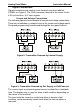
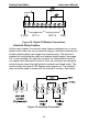
Figure 10: Voltage Input Connections
The meter is capable of accepting any voltage from -10 VDC to +10 VDC.
Modbus RTU Serial Communications
Serial communications connection is made to an RJ45 connector labeled
M-LINK on Figure 6. For interfacing to the APM, use the PMA-01 for RS-
232, or the PMA-03 for RS-485. The same port is used for interfacing
with all expansion modules (e.g. external relays, digital I/O).
Use the PMA-02 meter copy cable for meter-to-meter interfacing for
cloning purposes (i.e. copying settings from one meter to other meters).
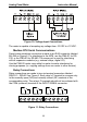
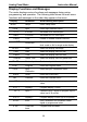
Relay Connections
Relay connections are made to two six-terminal connectors labeled
RELAY1 – RELAY4 on Figure 6. Each relay’s C terminal is common only
to the normally open (NO) and normally closed (NC) contacts of the
corresponding relay. The relays’ C terminals should not be confused with
the COM (common) terminal of the INPUT SIGNAL connector.
Figure 11: Relay Connections
CNONO NC NC C
RELAY4 RELAY3
4365 21
CNONO NC NC C
RELAY2 RELAY1
4365 21