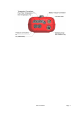
DWYER 1207A Flue Gas Analyzer Dwyer Instruments Inc P.O.
CONTENTS Page No: DWYER 1207A USER GUIDE 3 1. ANALYZER FEATURES AND KEYPAD 4-5 2. BEFORE USING THE ANALYZER FOR THE FIRST TIME 6 3. BEFORE USING THE ANALYZER EVERY TIME 7 4. USING THE ANALYZER AND ITS FOUR BUTTONS 5. USING THE DWYER 1207A AS A THERMOMETER OR PRESSURE METER 8-9 10 6. USING THE ROTARY DIAL (STARTING FROM MENU) 11-13 7. MAIN MENU FUNCTIONS 14-17 8. MEASURING MODES 18-24 9.
DWYER 1207A User Guide The DWYER 1207A Combustion Analyzer measures O2, differential temperature, differential pressure and CO. It calculates efficiency (Nett, Gross or Condensing), losses, the CO/CO2 ratio, Poison Index, excess air and CO air free in ppm only. The analyzer can be upgraded with the addition of a Nitric Oxide sensor either on initial purchase or as a retrofit as part of an annual service procedure.
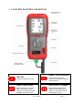
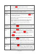
1. ANALYZER FEATURES AND KEYPAD PUMP / CAL PRESSURE ON / OFF Turns the analyzer ON / OFF Turns the pump ON / OFF Press for 2+ seconds to zero the pressure sensor PRINT / BACKLIGHT LINE SELECT / FREEZE Press to print “live” or “frozen” data. Press again to abort.
1207A manual Page 5
2. BEFORE USING THE ANALYZER FOR THE FIRST TIME: Turn over the analyzer, remove its’ protective rubber sleeve and fit 4 “AA” batteries in the battery compartment. Take great care to ensure they are fitted with the correct battery polarity. Then replace the battery cover and protective rubber sleeve. Always check that the analyzer is working correctly after replacing batteries. Set the analyzer’s correct time, date, fuel source, etc.
3. BEFORE USING THE ANALYZER EVERY TIME: Check the water trap is empty and the particle filter is not dirty: - To empty water trap, unplug its’ rubber stopper and re-plug once it is empty. - To change the filter, remove protective rubber sleeve, pull out the water trap unit from the analyzer, remove the water trap’s particle filter from its’ spigot and replace. Reconnect the water trap and rubber protective sleeve.
4. USING THE ANALYZER AND ITS FOUR BUTTONS: Switching ON the Analyzer Press to switch the unit ON in fresh air outside the property about to be tested. This lets the analyzer auto calibrate its’ sensors properly. On switch on, the analyzer beeps four times and displays the fuel previously selected, the date and time and model number. Its’ bottom line counts down from 60 until the sensors are ready to use – This normally takes 20 - 30 seconds but may take longer as sensors get older.
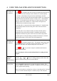
Backlight Press and hold to toggle the display's backlight. Note: use of the backlight increases the current drain on the batteries. Tasklight Switching PUMP on / off Comes on with the display's backlight... see above. The analyzer normally operates with the pump on. Press to switch the pump off and on. quickly When the pump is switched off, the analyzer displays "PUMP OFF" approx every 30 seconds. NOTE: the pump will not switch off if the CO reading is above 20 ppm.
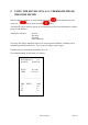
5. USING THE DWYER 1207A AS A THERMOMETER OR PRESSURE METER With the analyzer switched off, press and hold down the release the button, then release the button and then press and button. The DWYER 1207A will now operate as a fixed display pressure meter/thermometer with the pump off and inhibited. The display will show: pressure flue temp inlet temp differential temp The rotary dial display indications will now be locked apart from MENU. Readings can be held and logged in the normal way.
6. USING THE ROTARY DIAL (starting from Menu): Rotating the dial selects the displayed parameter, unless MENU is selected or the pressure/temperature mode has been selected. ROTARY DIAL POSITIONS MENU Switches to MENU function. BAT Displays estimated battery life. If battery voltage falls below a pre-set limit, the display flashes "LOW BAT" every 10 seconds. See Page 6 to change the batteries or re-charge, if applicable. TIME Displays Time.
T Nett Displays the difference between flue and inlet / ambient temperatures. If the flue probe’s temperature sensor is broken or open circuit it displays - OC -. CO Displays Carbon Monoxide values in PPM as CO in ppm normalized ac COn Display value in mg/m3 as COm in mg/m3 normalized as COĦ NO (if fitted) Displays Nitric Oxide values in PPM as NO in ppm normalized as NOn Display value in mg/m3 as NOm in mg/m3 normalized as NOĦ PRS Display the measured pressure or draft value in user selected units.
The exception is: key must be pressed to confirm the STORE DELETE where the change and exit. If you rotate the dial before pressing the instrument will beep continuously. You must rotate the dial back to MENU and press before you can continue. In STORE View mode the rotary dial is used to select the saved parameter to be displayed. Use the / keys to change the Test number. To exit the View mode press 1207A manual .
7.
SETUP SET FUEL NATU GAS L OIL PROPANE BUTANE L.P.G.
PRESSURE SMOOTH OFF ON Select smoothing POINTS LOW HIGH Select decimal point resolution PS UNITS inH2O Select pressure units mBAR mmH2O Pa kPa PSI mmHg hPa STORE up to 255 sets of combustion test results can be stored VIEW TEST xxx Enter test number to be viewed then use rotary dial to select display. If less than 9 set of readings are stored rotate the dial then use the up/down buttons to change the LOG number. AUTO STO YES/NO If YES set logging time interval in minutes.
SCREEN CONTRAST SET xx Lighten or darken the display AUX Selected Fuel Pressure units COM Date CO air free O2 Reference value Assign the AUX rotary dial position HEADER Header 1 Header 2 2 lines each of 20 characters 1207A manual Page 17
8. MEASURING MODES MEASURING FLUE GASES After the countdown is finished and the analyzer is correctly set up, put its’ flue probe into the appliance’s sampling point. The ideal sampling point is at least two flue diameters downstream of any bend. Put the probe tip in the flue center. With balanced flues, make sure the probe is positioned far enough into the flue so no air can ‘back flush’ into the probe. Use the probe’s depth stop cone to fix it in flue diameters from 1/4 to 4/5 inch, 6 to 21 mm.
STANDARD COMBUSTION PRINTOUT DWYER 1207A 1.0 Serial No. 123456789 DATE TIME /product code /serial number /user header 1 /user header 2 11/01/09 09:53:23 .............................................. FUEL NATU GAS O2 % CO2 % CO ppm NO ppm FLUE oF INLT oF NETT oF 5.1 9.0 400 n/f 48 15 33 EFF (C) PRS INWG Losses % XAIR % 102.1 0.001 -2.1 32.1 CO/CO2 PI O2 ref % 0.0044 0.44 0.0 /NO sensor not fitted /condensing efficiency SMOKE...................................... ...............................
STORING A DRAUGHT MEASUREMENT TO PRINT WITH A COMBUSTION TEST Rather than print a draught test report and then a combustion test report it is possible to combine the two sets of results on one printout by taking a draught reading first and storing it for printing later. The following sequence must be followed: With PRESSURE on the top line and with the rotary dial pointing to Prs... and with the pump off.....
MEASURING PRESSURE The analyzer can be used to measure pressure by connecting tubing to the appropriate ports. Standard Pressure Report .... this mode is accessed via the MENU function. This mode allows a tightness test to be carried out automatically. The times for the test can be set by the user. From the start of the test the analyzer waits 60 secs to allow temperature stabilization, then records and displays the pressure reading at the start of a 120 second countdown.
MEASURING TEMPERATURE The analyzer can be used as a normal single input or differential thermometer, ideal for measuring flow and return temperatures or for setting up hot water temperature/flow on a combi boiler. Standard Temperature Report .... this mode is accessed via the MENU function. DWYER 1207A 1.0 Serial No. 123456789 .............................................. Temp Test .............................................. LOG TIME 05 10:15 11/01/09 o T1 F 54.1 o T2 F 24.1 o ∆T F 30.0 .............
MEASURING AMBIENT AIR (ROOM CO) The analyzer's CO sensor can be used to detect spillage from appliances. A standard spillage test can be conducted where the analyzer automatically records 16 sets of 1 minute samples and prints the results as below: Standard Room CO Report .... this mode is accessed via the MENU function. DWYER 1207A 1.0 Serial No. 123456789 .............................................. Room CO Test ..............................................
MEASURING FLUE DRAUGHT STANDARD DRAUGHT REPORT DWYER 1207A 1.0 Serial No. 123456789 .............................................. Draught .............................................. TIME 15:58 11/01/09 PRS INWG 0.54 .............................................. customer .............................................. appliance .............................................. Ref: ...............................................
9. WHEN YOU FINISH A COMBUSTION TEST Remove its’ probe from the flue - THE PROBE WILL BE HOT - and let it cool. Do not put the probe in water which will be sucked into the analyzer, damaging its’ pump and sensors. When the analyzer’s readings return to ambient levels, switch it off. The analyzer counts down from 30 before switch off with the pump running to self clean its sensors.
10. ANALYZER PROBLEM SOLVING If any problems are not solved with these solutions, contact us or an authorized repair center. Fault symptom Causes / Solutions • Oxygen too high • Air leaking into probe, tubing, water trap, connectors or internal to analyzer. • CO2 too low • Oxygen reading (- - - -) • CO reading (- - - -) • Oxygen cell needs replacing. • Analyzer was stored in a cold environment and is not at normal working temperature. • Oxygen cell or CO sensor needs replacing. • Pump is switched off.
11. ANALYZER ANNUAL RECALIBRATION AND SERVICE Although sensor life is typically more than two years, the analyzer should be re-calibrated and serviced annually to stop any long-term sensor or electronics drift or accidental damage. Local regulations may require more frequent re-calibration. Contact us or an authorized repair center for more information.
12. ANALYZER SPECIFICATION (NOTE MAY BE SUBJECT TO CHANGE) Parameter Resolution Accuracy Range Flue Temperature 0.1°C/F +2.0°C +0.3% reading 0-600°C / 32-1112oF Inlet Temperature (Internal Sensor) 0.1°C/F +1.0°C ±0.3% reading 0-50°C / 32-122oF Inlet Temperature (External Sensor) 0.1°C/F +2.0°C +0.3% reading 0-600°C / 32-1112oF Pressure Measurement 0.1 Pa +0.5 Pa +20 Pa 0.1 Pa +3 Pa +100 Pa +3% of reading +2000 Pa 0.01 hPa +3% of reading +80 hPa Oxygen 0.1% +0.
Pre-programmed Fuels Dimensions Weight Handset Probe Natural gas, Light Oil, Propane, Butane, LPG, Wood Pellets. 0.77kg / 2.2lb handset with protective cover 200mm / 7.9” x 45mm / 1.8” x 90mm / 3.5” L300mm / 11.8” x Dia 6mm / 0.25” with 200mm / 7.
13. ELECTROMAGNETIC COMPATIBILITY European Council Directive 89/336/EEC requires electronic equipment not to generate electromagnetic disturbances exceeding defined levels and have adequate immunity levels for normal operation. Specific standards applicable to this analyzer are stated below.
Appendix 1 - Main Parameter: Here are the legends used and what they mean: O2 : Oxygen reading in percentage (%). O2R: Oxygen reference setting. '----' means switched off or set to 0%. T Flue: Temperature measured by the flue gas probe in Centigrade or Fahrenheit. It displays ‘- OC -’ if the flue probe is disconnected. T Nett : Nett temperature calculated by deducting the AMBIENT or INLET temperature from the measured FLUE temperature.
BAT Displays the Battery power available in %. When the LO BAT symbol appears this indicates the batteries are at less than 10% of charge and should be replaced, readings may be affected if used with low power batteries. Warning: all stored readings are lost when the batteries are removed or become exhausted. DATE : Date shown as day, month and year. The order can be changed using the menu function. Date is recorded when each combustion test is printed.