
Owner's manual


S
PECIFICATIONS
I
nput Signal: 4 to 20 mA DC.
Input Impedance: 250 ±15 Ω.
Material: Aluminum diecasting.
Air Supply: 20 to 101 psig (1.4 to 7.0
bar).
Air Supply Connection: 1/4˝ NPT.
Gage Connection: 1/8˝ NPT.
Electrical Connection: Screw
Terminal.
Conduit Connection: 1/2˝ NPT.
Linearity: ±0.2% of FS.
Hysteresis: 1% of FS.
Sensitivity: ±0.2% of FS.
Repeatability: ±0.5% of FS.
Air Consumption: 0.10 scfm (3 LPM)
at 20 psig (1.4 bar) supply.
F
low Capacity: 28 scfm (80 LPM) at
2
0 psig (1.4 bar) supply.
Stroke: 0.5 to 6˝ (10 to 150 mm).
Enclosure Rating: IP66.
Operating Temperature:
165EL: -4 to 158°F (-20 to 70°C);
165EL-SS: -40 to 158°F (-40 to
70°C);
165EL-FM: -4 to 140°F (-20 to
60°C).
Weight: 165EL: 6.1 lb (2.7 kg);
165EL-SS: 12.6 lb (5.7 kg).
Agency Approvals: CE (165EL
only), FM (165EL only).
PROXIMITY DIV., DWYER INSTRUMENTS, INC.
P.O. BOX 358 • MICHIGAN CITY, INDIANA 46360 U.S. A.
Phone: 219/879-8000 www.dwyer-inst.com
Fax: 219/872-9057 e-mail: info@dwyermail.com
The Series 165EL PRECISOR
®
II Electro-Pneumatic Positioner is used for lin-
e
ar operation of pneumatic linear valve actuators by means of electrical controller
o
r control systems with an analog output signal of 4 to 20 mA or split ranges.
FEATURES
• There is no resonance in the range of 5 to 200 Hz.
• Perform 1/2 split control without any other substitutes.
• Easy to adjust zero and span.
• Easy to convert from reverse action to direct action or vice versa.
• Easy feedback connection.
• Fast and accurate response.
• Low air consumption.
• Designed as multi-port type for air tubing.
• Easy to install air tubing connection in any direction.
• Designed as block build structure for maintenance and repair.
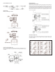
STRUCTURE
Series 165EL PRECISOR
®
II Electro-Pneumatic Linear Positioner
Specifications - Installation and Operating Instructions
Bulletin F-90
SPAN UNIT
TORQUE MORTOR
ZERO UNIT
BASE BODY
PILOT VALVE
FEEDBACK SHAFT
FEEDBACK LEVER
VENT UNIT
BASE COVER
JUNCTION BOX
PRINCIPLE OF OPERATION
Increase the input current signal to change lift position of valve. Force exerted by
(1) Torque Motor reduces Nozzle Back Pressure with increase in gap between (2)
Flapper and (3) Nozzle. Then (5) Spool moves upward and the (7) Seat opens
simultaneously. Air pressure of OUT1 pipe is discharged to (10) Actuator. As pres-
sure in the actuator chamber goes up, (12) Actuator Stem starts to move. The
movement of (12) Actuator Stem exerts force to the (a) Feedback Spring through
Feedback Shaft connections. Then (10) Actuator will stop at the point of force bal-
ance exerted by the input current signal and the feedback spring.
S
P
A
R
E
3
0
2
0
4
0
1
2
3
4
5
6
7
8
9
10
11
12
13
14
15
16
INPUT SIGNAL
4 ~ 20 mA
E
OUT1
OUT2
SUPPLY
6
-9/16
[
166.69]
6
-43/64
[
169.47]
2
X M8X1.25
1-25/32
[45.24]
4
-41/64
[
117.87]
2-49/64
[70.25]
1
-31/32
[
50.01]
4
X M8X1.25
STAINLESS STEEL VERSION
STANDARD VERSION
8-3/4
[225.30]
6-9/16
[166.69]
2X M8X1.25
4-9/16
[115.89]
1-25/32
[45.24]
1
-31/32
[
50.01]
4
X M8X1.25
2-3/4
[69.85]
3-19/32
[91.29]
3
-5/8
[
92.08]
Electro-Pneumatic
POSITIONER
Electro-Pneumatic
POSITIONER