
Owner's manual


BLOCK DIAGRAM OF 165EL
I
NSTALLATION
E
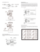
xample of attaching to actuator
Example 1.
C
ase of directly attaching to diaphragm valve.
Example 2.
Case of using a bracket.
Connection with Feedback Lever
Attach in the position that the valve stem and lever form a right angle when the
input signal is 50%. Attach to the position that the runout angle is within the range
of 10 to 30°.
INSTALLATION cont.
Direct Action & Reverse Action
Attach the cam in the procedure of loosening the hexagonal nut with flange first,
s
etting the actuator to the starting position and then setting the cam reference line
a
nd the bearing contact point of span adjusting arm unit to the same position. Do
n
ot apply the supply pressure when attaching the cam as otherwise it is very dan-
g
erous. When the positioner is shipped out, the cam is tentatively tightened to the
shaft. Be sure to firmly lock the cam to the lock nut [tightening torque 17.7 to 22.1
in-lbs (2.0 to 2.5 NM)].
AIR PIPING CONNECTION
Fully purge the pipe to remove foreign matter. Use a clean supply air fully
removed of humidity and dust. Use a Series AFR filter regulator to keep supply
air pressure constant.