INSTRUCTIONS FOR THE 16L SERIES MICROPROCESSOR BASED TEMPERATURE / PROCESS LIMIT CONTROL FM ® LOVE CONTROLS DIVISION Dwyer Instruments, Incorporated ® December, 1998 PO Box 338 m Michigan City, IN 46361-0338 (800) 828-4588 m (219) 879-8000 m FAX (219) 872-9057 www.love-controls.
CONTENTS MODEL IDENTIFICATION ...................................................................... 2 GETTING STARTED ............................................................................... 3 INSTALLATION ....................................................................................... 4 WIRING ................................................................................................... 5 Wiring for 4 to 20mA Transmitter inputs ...........................................
GETTING STARTED 1. Install the control as described on page 4. 2. Wire your control following the instructions on page 5. If you are using a two-wire transmitter as an input, see the drawing and instructions on page 6. Option wiring instructions are on Page 7. Option descriptions and specific instructions start on page 16. 3. Most controls do not need many (if any) program changes to work on your process.
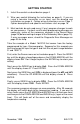
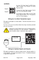
INSTALLATION Mount the instrument in a location that will not be subject to excessive temperature, shock, or vibration. All models are designed for mounting in an enclosed panel. Select the position desired for the instrument on the panel. If more than one instrument is required, maintain the minimum of spacing requirements as shown on the drawing below. Closer spacing will structurally weaken the panel, and invalidate the IP66, UL type 4 rating of the panel.
WIRING Do not run thermocouple or other class 2 wiring in the same conduit as power leads. Use only the type of thermocouple or RTD probe for which the control has been programmed. Maintain separation between wiring of sensor, auxiliary in or out, and other wiring. See the "Secure Menu" for input selection. For thermocouple input always use extension leads of the same type designated for your thermocouple. For supply connections use No. 16 AWG or larger wires rated for at least 75°C.
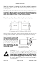
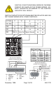
OUTPUTS + - For relay, NO (Order Code 3) or SSR (Order Code 1) outputs, 15 & 16 and 17 & 18 are Normally Open. Output A For relay, NC (Order Code 4) outputs, 15 & 16 and 17 & 18 are Normally Closed. Output B + - For Pulsed DC (Order Code 2) and DC SSR (Order Code 8) outputs, 15 & 17 are positive and 16 & 18 are negative. Wiring for 4 to 20mA Transmitter inputs Wire power and outputs as shown above. Two-wire transmitters wire as shown below.
CAUTION: DO NOT RUN SIGNAL WIRING IN THE SAME CONDUIT OR CHASE AS THE POWER WIRING. ERRATIC OPERATION OR DAMAGE TO THE CONTROL CIRCUITRY WILL RESULT. SWITCH CONTACTS FOR OPTION 948 MUST BE ISOLATED AND CAN NOT SHARE WIRING WITH OTHER CONTROLS.
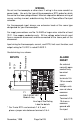
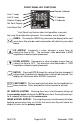
FRONT PANEL KEY FUNCTIONS Remote Indicator Limit 1 Lamp Limit 2 Lamp °F Indicator Process Display °C Indicator Set Point Display Limit Reset Key* * Limit Reset key flashes when limit condition is present. Keys are illuminated when pressed. Key functions are as follows: INDEX: Pressing the INDEX key advances the display to the next menu item. May also be used in conjunction with other keys as noted below. UP ARROW: Increments a value, changes a menu item, or selects the item to ON.
INDEX & ENTER: Pressing these keys simultaneously and holding them for 5 seconds allows recovery from the various error messages. The following menu items will be reset: S1iH: Set Point 1 limit inhibit S2iH: Set Point 2 limit inhibit OPEn InP: Input error message CHEC CAL: Check calibration error Correct the problems associated with the above conditions before using these reset keys. More than one error could be present. Caution is advised since several items are reset at one time.
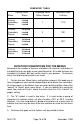
PASSWORD TABLE Menu Security Level Status Displayed Value When Viewed Password Value To Enter Primary Secondary Secure Locked Locked Locked 1 1110 Primary Secondary Secure Unlocked Locked Locked 2 1101 Primary Secondary Secure Unlocked Unlocked Locked 3 1011 Primary Secondary Secure Unlocked Unlocked Unlocked 4 111 NOTATION CONVENTIONS FOR THE MENUS Because of the number of features available in this control, information is included that may not apply to your specific control.
THE HOME DISPLAY The home display is the normal display while the control is operating. The HOME display may be programmed to operate in one of three different ways. This is controlled by the diSP menu item in the Secure Menu. If diSP is set for Pro, the HOME display will show only the Process Variable (the temperature, pressure, flow, RH, etc., that is being measured) on the top display with the bottom display blank.
POL = Lowest desired scale reading - ((Minimum desired analog output) * K). Next select whether you want the retransmission signal to follow the Process Variable or the Set Variable. Usually the Process Variable is sent to recorders or other data acquisition devices. Usually the Set Variable is sent to other controls to be used as an analog remote set point. If you want the analog retransmission signal to follow the PV, in the Secondary Menu set POSr to InP.
Wire the communication lines as shown on Page 7. Wiring for the RS-485 is run from control to control in a daisy chain fashion with a termination resistor (120 ohms) across the transmit and receive terminals of the last control in the chain. Select the control address and communication baud rate with the Addr and bAUd menu items in the Secure Menu. THE BAUD RATE AND ADDRESS MENU ITEMS WILL TAKE EFFECT ON THE NEXT POWER UP OF THE CONTROL.
MENU SELECTIONS PRIMARY MENU Press INDEX to advance to the next menu item. Press UP ARROW or DOWN ARROW to change the value in the display. Press ENTER to retain the value. #SP1 SP1 (Option 948, 4-Stage Set Point) or Set Point 1 Adjust, Limit Point 1. SP2 Set Point 2 Adjust (if equipped), Limit Point 2. SECONDARY MENU Hold UP ARROW & ENTER. Press INDEX to advance to the next menu item. Press UP ARROW or DOWN ARROW to change the value in the display. Press ENTER to retain the value.
SP (Option 948, 4-Stage Set Point) Active Set Point Stage. Select 1SP1, 2SP1, 3SP1, 4SP1. (See Page 17 for more detail.) 1SP1 Set Menu Items to display Stage 1 for view and change access. If SPSA is set for Int, 1SP1 is made active. 2SP1 Set Menu Items to display Stage 2 for view and change access. If SPSA is set for Int, 2SP1 is made active. 3SP1 Set Menu Items to display Stage 3 for view and change access. If SPSA is set for Int, 3SP1 is made active.
POH (Option 934, 936, Analog Retransmission Output) Process Output High: Select from any value greater than POL to +9999°F, +5530°C, or 9999 counts. LOrE (Option 992, 993, Serial Communications) Local / Remote Status: Select LOC or rE. LOC The host computer is advised not to send remote commands. Any write commands sent to the controls will be rejected. rE The host computer is allowed to send write commands.
SECURE MENU Hold UP ARROW & ENTER for 5 Seconds. Press INDEX to advance to the next menu item. Press UP ARROW or DOWN ARROW to change the value in the display. Press ENTER to retain the value. OUTPUTS ARE DISABLED (TURNED OFF) WHILE CONTROL IS IN SECURE MENU. SECr Security Code: See the Security Level Selection and the Password Table in this manual, in order to enter the correct password. InP Input Type: Select one of the following. Refer to the Input wiring section for the proper wiring.
dPt Decimal Point Positioning: Select 0, 0.0, 0.00, 0.000, or .0000. On temperature type inputs this will only effect the Process Value, SP1, SP2, and InPC. For Current and Voltage Inputs all Menu Items related to the Input will be affected. 0 No decimal Point is selected. This is available for all Input Types. 0.0 One decimal place is available for Type J, K, E, T, L, RTD’s, Current and Voltage Inputs. 0.00 Two decimal places is only available for Current and Voltage Inputs. 0.
SCAH Scale High: Select 100 to 9999 counts above SCAL. The total span between SCAL and SCAH must be within 11998 counts. Maximum setting range is -1999 to +9999 counts. For Current and Voltage inputs, this will set the high range end. Viewable only for Thermocouple and RTD ranges. SPL Set Point Low: Select from the lowest input range value to SPH value. This will set the minimum SP1 or SP2 value that can be entered. The value for SP1 or SP2 will not stop moving when this value is reached.
S1St Set Point 1 State: Select Eng or dEng. Eng Output Energized. The output device (per Order Code) will be energized at set point. (Normally Open contacts will close, Normally Closed contacts will open.) dEng Output De-energized. The output device (per Order Code) will be de-energized at set point. (Normally Open contacts will open, Normally Closed contacts will close.) S1LP Set Point Lamp: Select O on or OoFF. O on Lamp ON when Output is ON (energized). OoFF Lamp OFF when Output is ON (energized).
S2St Set Point 2 State: Select Eng or dEng. Eng Output Energized. The output device (per Order Code) will be energized at set point. (Normally Open contacts will close, Normally Closed contacts will open.) dEng Output De-energized. The output device (per Order Code) will be de-energized at set point. (Normally Open contacts will open, Normally Closed contacts will close.) S2LP Set Point 2 Lamp: Select O on or OoFF. O on Lamp ON when Output is ON (energized). OoFF Lamp OFF when Output is ON (energized).
DIAGNOSTIC ERROR MESSAGES DISPLAY MEANING SP OUTPUTS ACTION REQUIRED No display lighted Set point Check that the power supply is Display is blank. Instrument is not get- outputs inactive on, or that the external fuses ting power, or the Alarm inactive are good. supply voltage is too low.
DIAGNOSTIC ERROR MESSAGES DISPLAY UFL or OFL SP OUTPUTS MEANING ACTION REQUIRED Set point Underflow or OverInput signals may normally go flow: Process value outputs active above or below range ends. If has exceeded input Alarm active not, check input and correct. range ends. UFL or OFL will sequence to display one of these messages if the InPt is set for a time value. Set point outputs inactive Alarm active To reset use the INDEX & ENTER keys.
SPECIFICATIONS Selectable Inputs: Thermocouple, RTD, DC Voltage, or DC Current selectable. Input Impedance: Thermocouple = 3 megohms minimum. RTD current = 200 µA. Current = 10 ohms. Voltage = 5000 ohms. Sensor Break Protection: De-energizes output(s) to protect system after customer set time. (See InPt in Secondary Menu.) Set Point Range: Selectable (See Range Chart Page 26). Display: Two 4 digit, 7 segment 0.3" high LEDs.
Output Ratings: AC SSR: 2.0 A @ 240 Vac at 25 °C (77°F). Derates to 1.0 A @ 55° C (130°F). DC SSR: 1.75 A @ 32 Vdc maximum. Relay: SPST, 3 A @ 240 Vac resistive; 1.5A @240 Vac inductive; Pilot duty rating 240 VA, 2 A @ 120 Vac or 1 A 240 Vac. Switched Voltage (isolated): 15 Vdc @ 20 mA. Panel Cutout: 45 mm x 45 mm (1.775" x 1.775"). Depth Behind Mounting Surface: 121.6 mm (4.79"), maximum. Weight: 220 g (8 oz). Agency Approvals: FM, CE. Front Panel Rating: IP66, (NEMA4X).
Input Ranges (Field Selectable) Thermocouple Types Input Type Type J or L* Type K* Type T* Type E* -350 to +750 -212 to +398 -100 to +1800 -73 to +982 Type S Type B Type C 0 to 3200 -17 to +1760 +75 to 3308 +24 to 1820 0 to 4208 -17 to 2320 Range 1°F -100 to +1600 -200 to +2500 1°C -73 to +871 -129 to +1371 Input Type Type R Range 1°F 0 to 3200 1°C -17 to +1760 Input Type Type N* Range 1°F -100 to +2372 1°C -73 to +1300 * These Input Types can be set for 0.1° display.
December, 1998 DIMENSIONS Page 27 of 28 L LM RESET LM FM ® All dimensions in millimeters (inches). Panel cut out is 45 +0.6 (1.77 +0.02) square.
LOVE CONTROLS DIVISION Dwyer Instruments, Incorporated ® 949-1270 PO Box 338 m Michigan City, IN 46361-0338 (800) 828-4588 m (219) 879-8000 m FAX (219) 872-9057 www.love-controls.