
Owner's manual


3
. Set the rotation position of the actuator stem as the initial zero point, which is 0%
s
troke. For a spring return type actuator, the actuator stem is always rotated to the
z
ero point without supply pressure, making it easy to check the zero point. If the
a
ctuator is double-acting, check whether the rotation direction of the actuator is
clockwise or counter-clockwise, or the rotation direction of the actuator using
supply pressure.
4
. Set the actuator stem as the initial zero point and install a fork lever as showing
i
n the following picture. Confirm the position of initial zero point when the actuator
s
tem is turned clockwise and counter-clockwise. Installation angle of the fork lever
s
hould be about 45 degrees based on the linear shaft. But the angle is not related
to the NAMUR shaft.
Installation Position of Fork Lever
5. Once the fork lever position is set, lock the check nuts on the bottom of the fork
lever by turning clockwise. Set the upper height of the fork lever to .24 to .43˝ (6 to
11 mm) lower than the upper height of the bracket.
6. Attach the Series 295 unit to the bracket. Fix the clamping pin on the main shaft
center of the Series 295 into the hole of the fork lever. Insert the connection bar
attached on the main shaft lever into the fork lever slot to be locked by the fork lever
spring. This is to fit the main shaft of the Series 295 to the center of the actuator
stem. If they are not fitted correctly, too much force on the main shaft will greatly
reduce product durability.
7. Attach the Series 295 base and the bracket with hex bolts and plate washers. It
is best to lock the bracket and Series 295 together by inserting four bolts after
checking the position.
PIPING CONNECTION
Conditions of Supply Pressure
1. Dry air with a dew point that is at least 50°F (10°C) lower than that of the ambient
temperature.
2
. Free from solid particles. Result of being passed through 5 micron or finer filter.
3
. Does not contain oil or lubricating oil.
4
. Comply with ANSI/ISA-57.3 1975(R1982) or ISA S7.3-1975(R1981).
5
. Not used beyond the range of 20 to 100 psi (140 to 700 kPa).
6. Set supply pressure of air filter regulator to 10% higher than operating pressure
of actuator.
C
onditions of Pipe
1
. Remove foreign objects from inside of pipe.
2
. Do not use squeezed or broken pipe.
3
. To maintain flow rate of Series 295, use a pipe with inner diameter of greater than
.24˝ (6 mm) (outer diameter .39˝ (10 mm)).
Piping Connection With Actuator
S
eries 195 and Series 295 can operate either single or double acting actuators.
Single Acting Actuator
To operate a single acting actuator, connect OUT1 port to actuator supply
pressure port. Close off the OUT2 port with the supplied 1/4˝ NPT plug.
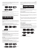
Power Connection
450
C
ounter-Clockwise
SMART POSITIONER
P
iping Connection Example of Series 195 with Single Acting Actuator
Piping Connection Example of Series 295 with Single Acting Actuator
Terminal Plate of Series 195 & 295
450
Clockwise
1. To prevent ingress of moisture, oil and dust, give careful
consideration to the choice of supply pressure compressor and
piping.
2. It is recommended to attach a filter or air filter regulator in front of the supply port
of the Series 295 unit..
NOTICE
1. Before connecting terminal, power must be shut off.
2. Use ring type terminal against oscillation, impact, etc.
3. Series 195 and 295 positioners use 4 to 20 mA DC for power. Minimum supply
current is 3.2 mA (standard type) and 3.8 mA (HART
®
type). Maximum supply
current must not exceed 24 mA. In order to protect the Smart Positioner, the ground
terminals should be grounded.
4. Use twisted cable with conductor sectional area at least 0.0019 in
2
(1.25 mm
2
),
and suitable for 600V as on conductor table of NEC Article 310. Outer diameter of
cable should be .25 to .39˝ (6.35 to 10 mm). Use shielded wire against
electromagnetic waves and noise.
5. Do not install the cable near equipment such as a high-capacity transformer or
motor.
CAUTION
P
age 4