Bulletin AV-4-AFH2 Model AFH2 Air Flow Hood Specifications - Installation and Operating Instructions DWYER INSTRUMENTS, INC. P.O. BOX 373 • MICHIGAN CITY, INDIANA 46360, U.S.A. Phone: 219/879-8000 Fax: 219/872-9057 www.dwyer-inst.com e-mail: info@dwyer-inst.
Bulletin AV-4-AFH2 Model AFH2 Air Flow Hood Specifications - Installation and Operating Instructions 24 SQ. [609.60] 38 [965.20] 8 [203.20] MOUNTING PLATE 18-1/2 [469.90] HOOD FRAME ASSEMBLY The Model AFH2 Air Flow Hood is designed to measure differential air pressure in and around commercial and industrial air handling systems. The AFH2 Air Flow Hood maintains a running average of measurements in the desired system.
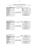
Page 3 SECTION 2: DESCRIPTION 2.1 Power Supply The manometer is powered by one 9V battery or equivalent. The battery is contained in the battery compartment, which is accessible by removing the clip-on cover on the back of the digital manometer. To conserve battery power, the instrument has an AUTO-OFF feature that may be turned on or off. If you wish to learn how to use this feature of the digital manometer, please see page 6 (Setting the Switch Off Period). 2.1.
Page 4 Connecting the Digital Manometer 1. Attach the instrument to the steel plate. 2. Connect the blue hose to the Reference port on the instrument. Connect the clear hose to the Signal In port on the instrument. 2.3 Disassembly Disassembly is essentially the reverse of the assembly procedure. Disconnecting the Instrument 1. Disconnect the hoses from the digital manometer. 2. Detach the manometer from the metal plate. 3. Collapse the capture hood. 4. Store the instrument and components in the travel case.
Page 5 MICROMANOMETER DISPlAY 2 3 1 4 ON: Is used in conjunction with the enable key to switch on the instrument. 5 OFF: Is used in conjunction with the enable key to switch off the instrument. 6 8 KEY PAD CONTROlS: ENABlE: Protects against accidental switching of the instruments power source. 7 1. Whenever the auto zero sequence is initiated manually or at powerup, auto zero will be displayed until the cycle is complete.
Page 6
Page 7
Page 8
Page 9
Page 10
Page 11
Page 12
Page 13
Page 14 Only use genuine cable and diskette. If any other accessories are used or the incorrect downloading software is used then the guarantee on the instrument and the accessories becomes null and void.
Page 15 Making Measurements The capture hood can be used on either supply or exhaust flows. Which of these factors you will use depends on where in the duct you wish to measure the air flow rate. Press the UNITS key until L/s, m3/hr or cfm appears on the right-hand-side of the display. Use the Up and Down arrow keys to toggle between the Hood Supply and Hood Exhaust factors, which are shown in the top line of the display.
Page 16 ©Copyright 2013 Dwyer Instruments, Inc. Printed in U.S.A. 9/13 DWYER INSTRUMENTS, INC. P.O. BOX 373 • MICHIGAN CITY, INDIANA 46360, U.S.A. Phone: 219/879-8000 Fax: 219/872-9057 FR# R1-443748-00 Rev. 3 www.dwyer-inst.com e-mail: info@dwyer-inst.