
User Manual


I
nductive Loads
Possible causes -
An electromagnetic relay, electromagnetic
solenoid, electromagnetic counter with inductive
component as circuit load.
Capacitive Loads
Possible causes -
A capacitor connected in series or parallel with
Reed Switch control. In a closed circuit, a cable
length (usually greater than 50m [162.5 ft.])
used to connect reed switch may also introduce
static capacitance.
Lamp Loads
Possible causes -
A tungsten filament lamp load.
©Copyright 2014 Dwyer Instruments, Inc.
Printed in U.S.A. 7/14
FR# 82-440677-00 Rev. 5
I
nstallation Notes - Do not subject
r
eed switch controls to excessive
s
hock or vibration or any of the
following:
• Bending or placing force loads on
reed switch housing.
•
Over-torquing fittings on reed
s
witch housing.
•
Placing pull-out force on lead wires.
C
IRCUIT INFORMATION FOR REED SWITCH PROTECTION
Read information below before installing your new reed switch control!
Exceeding the current capacity of this Reed Switch control may cause FAULTY OPERATION! Be aware of the inductive and capacitive or lamp loads you may be placing on
you Reed Switch Control. The circuits below outline possible solutions to preventing overloads due to inrush or surge currents exceeding maximum or when the switch current
a
nd product of the inductive back EMF exceed the switch’s power rating. Also the circuit for prevention of overload when switching filament lamps (low “cold” resistance) is
o
utlined below. Failure to follow these measures to protect Reed Switch Contacts may cause the contacts to weld together or result in premature wear.
Indicating arrows are
provided on the stem
ends to confirm float
alignment.
Do not exceed 1.5 pounds/
foot (2 n/m) tightening
torque. Excessive torque
may cause premature switch
element or housing failure.
Avoid installations where
wiring entering the device is
submerged or exposed to
excessive amounts of liquid
or humidity condensate.
Gasket seal for internal
mounting units should be pre-
assembled before insertion
through tank wall. Wall thick-
ness should not exceed 1/8"
(3 mm).
When preparing wires for
termination, avoid pulling
against the resin seal or
end plug of the float switch.
Units with tapered pipe
threads should be treated
with Teflon based thread
compound or tape before
insertion in fitting. Sufficient
torque is achieved at hand-
tight plus one half turn.
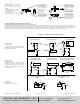
Possible Circuit Solutions Indicated by Dashed Lines
D
IODE SUPPRESSION
DIODE
INDUCTIVE
LOAD
PIV DIODE > V
REED
SWITCH
REED
SWITCH
USED IN
AC CIRCUITS
VARISTER
VARISTER PROTECTION
INDUCTIVE
L
OAD
R
C SUPPRESSION
R
C
INDUCTIVE PROTECTION FOR
CABLE LENGTH CAPACITANCE
LOAD
REED
SWITCH
Cable Length
over 50 meters
[162.5 ft.]
REED
SWITCH
RESISTOR PROTECTION
FOR CAPACITIVE LOAD
SURGE LIMITER FOR
CAPACITANCE IN SERIES
REED
SWITCH
CURRENT LIMITING RESISTOR
IN SERIES
CURRENT LIMITING RESISTOR
IN PARALLEL
REED
SWITCH
REED
SWITCH
INDUCTIVE
LOAD
REED
SWITCH
SWITCH
[
uf]
10
C
R
10*I
(1+50/E)
SWITCH
2
C
LOAD
SWITCH
SWITCH
LOAD
C
R
L =0.5~ 5 mH
P
+V
R
A
P
L
R
A
+V
R = 50~500 Ohms
R
B
P
L
L = 0.5~5 mH
P
+V
R
L
R
R
V-0.12 R
L
2
+V R
L
5R > R
L
R
DWYER INSTRUMENTS, INC.
Phone: 219/879-8000 www.dwyer-inst.com
P.O. BOX 373 • MICHIGAN CITY, INDIANA 46360, U.S.A. Fax: 219/872-9057 e-mail: info@dwyermail.com