
Manual

INSTALLATION
Unpack switch and remove any packing material found inside lower housing or float
c
hamber.
S
witch must be installed with body in a horizontal plane and arrow on side pointing
down.
If switch has an external float chamber (tee), connect it to vertical sections of 1˝
NPT pipe installed outside vessel walls at appropriate levels. If unit has no external
f
loat chamber, it must be mounted in a 1˝ NPT half coupling welded to the vessel
w
all. The coupling must extend through the wall.
Inspect and clean wetted parts at regular intervals.
ELECTRICAL CONNECTIONS
C
onnect wire leads in accordance with local electrical codes and switch action
r
equired. N.O. contacts will close and N.C. contacts will open when liquid level
c
auses float to rise. They will return to “normal” condition on decreasing liquid level.
Black = common, Blue = N.O. and Red = N.C.
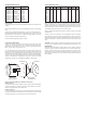
For units supplied with both internal ground and external bonding terminals, the
ground screw inside the housing must be used to ground the control. The external
bonding screw is for supplementary bonding when allowed or required by local
code. When external bonding conductor is required, conductor must be wrapped a
minimum of 180° about the external bonding screw. See below. Some CSA listed
models are furnished with a separate green ground wire. Such units must be
equipped with a junction box, not supplied but available on special order.
EC-Type Certificate IECEX and KC Installation Instructions:
Cable Connection
The cable entry device shall be certified in type of explosion protection flameproof
enclosure “d”, suitable for conditions of use and correctly installed. For Ta ≥ 65°C
cable and cable gland rated ≥ 90°C shall be used.
Conduit Connection
An Ex d certified sealing device such as a conduit seal with setting compound shall
be provided immediately to the entrance of the valve housing. For Ta ≥ 65°C wiring
and setting compound, in the conduit seal, rated ≥ 90°C shall be used.
Note: ATEX, IECEx and KC units only: The temperature class is determined by the
maximum ambient and or process temperature. Units are intended to be used in
a
mbient of -20°C≤ Tamb ≤75°C. Units may be used in process temperatures up to
1
05°C providing the enclosure and switch body temperatures do not exceed 75°C.
T
he standard Temperature Class is T6 Process Temp ≤75°C.
Refer to Certificate No: IECEx DEK 11.0039 for conditions of safe use for IECEx
compliant units.
A
ll wiring, conduit and enclosures must meet applicable codes for hazardous
a
reas. Conduits and enclosures must be properly sealed. For outdoor or other loca-
t
ions where temperatures vary widely, precautions should be taken to prevent con-
densation inside switch or enclosure. Electrical components must be kept dry at all
times.
CAUTION: To prevent ignition of hazardous atmospheres, disconnect the device
f
rom the supply circuit before opening. Keep assembly tightly closed when in use.
M
AINTENANCE
Inspect and clean wetted parts at regular intervals. The cover should be in place at
all times to protect, the internal components from dirt, dust and weather and to
maintain hazardous location ratings. Disconnect device from the supply circuit
before opening to prevent ignition of hazardous atmosphere. Repairs to be con-
ducted by Dwyer Instruments, Inc. Units in need of repair should be returned to the
factory prepaid.
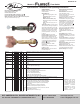
M
AXIMUM PRESSURE CHART
W
ETTED MATERIALS CHART
Model Number
L6EPB-B-S-3-A
L6EPB-B-S-3-B
L
6EPB-B-S-3-C
L
6EPB-B-S-3-H
L
6EPB-B-S-3-O
L
6EPB-S-S-3-A
L6EPB-S-S-3-C
L6EPB-S-S-3-L
L6EPB-S-S-3-O
L
6EPB-S-S-3-S
Float
Cylindrical SS
Polypropylene
R
ound SS
R
ound SS
P
olypropylene
C
ylindrical SS
Round SS
Round SS
Polypropylene
P
olypropylene
P
ressure Rating
psig (kg/cm
2
)
200 (13.8)
250 (17.2)
3
50 (24.1)
2
50 (17.2)
1
000 (69)
2
00 (13.8)
350 (24.1)
350 (24.1)
2000 (138)
2
000 (138)
Model
B-S-3-A
B
-S-3-B
B
-S-3-C
B
-S-3-H
B
-S-3-O
S-S-3-A
S-S-3-C
S-S-3-L
S
-S-3-O
S
-S-3-S
Brass
X
X
X
X
X
Bronze
X
X
Ceramic
X
X
X
X
X
X
X
X
X
X
Polypropylene
X
X
X
X
X
301SS
X
X
X
X
X
X
X
X
X
X
303SS
X
X
X
X
304SS
X
X
X
X
X
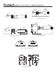
FRONT VIEW DETAIL SIDE VIEW DETAIL
CLAMP
SCREW
LOCKWASHER
CONDUCTOR