
User Manual


4
basic
tional
ptions
rior to
paces
be a
es are
INSTALLATION
Mount the instrument in a location that will not be subject to excessive temperature, shock,
or vibration (see Specifications for specific tolerances). All models are designed for mounting
in an enclosed panel.
Select the position desired for the instrument on the panel. Prepare the panel by cutting and
deburring the required opening.
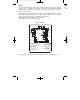
From the front of the panel, slide the housing through the cut out. The housing gasket should
be against the housing flange before installing.
From the rear of the panel slide the mounting collar over the housing. Hold the housing with
one hand and using the other hand, push the collar evenly against the panel until the springs
are compressed. The ratchets will hold the mounting collar and housing in place.
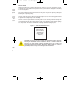
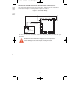
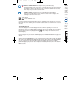
Figure 1 – Panel Cut Out Dimensions
CAUTION: It is not necessary to remove the instrument chassis from the
housing for installation. If the instrument chassis is removed from the
housing, you must follow industry standard practice for control and
protection against Electro-Static Discharge (ESD). Failure to exercise
good ESD practices may cause damage to the instrument.
Panel cut-out:
3.620 x 3.620 in,
+0.032/-0.000
(92 x 92 mm,
+0.8/-0.0)
lable
s
L-20:L-20 2/24/11 9:59 AM Page 4