
User Manual


5
Pump 1 Over Temp
Pump 2 Over Temp
Voltage
Current
Seal
Sensor
Inputs
Pump 1
Alarm 1
Contacts
Alarm 2
Contacts
Pump 1
Output
Pump 2
Output
24 VDC
@
50 mA
Isolated
Pump 2
N.O.
COM.
N.O.
COM.
NOTES:
1. For supply connections use
No. 16 AWG or larger wires rated
for at least 167˚F (75˚C) or, in
accordance with an equivalent
national standard.
2. Maximum ambient temperature
rating 131˚F (55˚C).
3. Use copper conductors only.
4. Terminals 1-6, 11, 12, 21-32
are class 2 "SELV".
Line Input
100 to 240 VAC 50-
400 Hz. Single PH.
132 to 240 VDC 5VA.
Max. Output Ratings:
Relay: 10A @ 240 VAC Res.
1/4 HP @ 120 VAC
1/3 HP @ 240 VAC
Alarm: 3A @ 240 VAC Res.
1/10 HP, 120 VAC
290-3120
Analog Retransmission
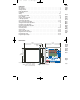
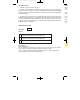
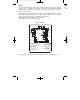
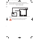
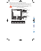
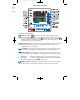
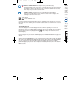
Figure 2 - Wiring
WIRI
Wire
show
WIRING
Do not run transmitter wiring or other class 2 wiring in the same conduit as power leads. Use
only the probe or transmitter for which the control has been programmed. Maintain
separation between wiring of sensor, auxiliary in or out, and other wiring. See the ˝Secure
Menu˝ for input selection.
Supply connections should be made in accordance with the National Electrical Code per
Article 300, and local regulations. All line voltage output circuits must have a common
disconnect and be connected to the same pole of the disconnect.
Input wiring for probe or transmitter is rated CLASS 2.
Control wiring is as shown in Figure 2 below.
For
trans
If not using pump over temperature inputs then jumper terminals 22 to 23 and 22 to 24.
L-20:L-20 2/24/11 9:59 AM Page 5