
Install Instructions

Bulletin E-71
Specifications - Installation and Operating Instructions
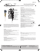
Vane Operated Flow Switch
U.L. AND C.S.A. TYPE
INCLUDES 16 GA.
LEADS, 6 [152.4] LONG.
ATEX/IECEx VERSION
INCLUDES TERMINAL
BLOCK
EXPLOSION-PROOF HOUSING
WITH 3/4 FEMALE NPT
CONDUIT CONNECTION
SWITCH BODY, SAE 72 BRASS
OR 316 STAINLESS STEEL
1-1/2 MALE NPT
PROCESS CONNECTION
MAGNET KEEPER,
430 STAINLESS STEEL
FIVE LAYER VANE,
316 STAINLESS STEEL,
DESIGNED FOR 1-1/2˝ TO 8˝ PIPES.
USABLE IN LARGER PIPE SIZES.
VANE BLOCK,
316 STAINLESS STEEL
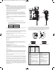
3-11/32
[84.93]
2-23/32
[69.06]
1-5/8 [41.28]
CLEARANCE FOR
COVER REMOVAL
8
[203.20]
6-3/4
[171.45]
1 [25.40]
4-11/16
[119.06]
SPECIFICATIONS
Service: Gases or liquids compatible with wetted materials.
Wetted Materials: Vane: 316 SS; Body: Brass or 316 SS standard; Magnet
Keeper: 430 SS standard, 316 SS optional; Options: Other materials also
available, consult factory (e.g. PVC, Hastelloy, Nickel, Monel, Titanium).
Temperature Limit: -4 to 275°F (-20 to 135°C) standard, MT high temperature
option 400°F (205°C) [MT option not UL, CSA, ATEX or IECEx] ATEX and IECEx
options, ambient temperature -4 to 163°F (-20 to 73°C); Process temperature -4
to 163°F (-20 to 73°C).
Pressure Limit: Brass body 1000 psig (69 bar), 316 SS body 2000 psig (138
bar), optional 5000 psig (345 bar) available with 316 SS body and SPDT switch
only.
Enclosure Rating: Weatherproof and Explosion-proof. Listed with UL and CSA
for Class I, Groups C and D; Class II, Groups E, F, and G.
ATEX 2813 II 2 G Ex db IIB T6 Gb -20°C≤Tamb≤73°C.
-20°C≤Process Temp≤73°C.
EU-Type Certificate No.: KEMA 03 ATEX 2383.
ATEX Standards: EN60079-0: 2012 + A11: 2013; EN60079-1: 2014.
IECEx Certified: For Ex db IIB T6 Gb -20°C≤Tamb≤73°C. -20°C≤Process
Temp≤73°C.
IECEx Certificate of Conformity: IECEX DEK 11.0071.
IECEx Standards: IEC 60079-0: 2011; IEC 60079-1: 2014.
Zone I. Also FM approved.
Switch Type: SPDT snap switch standard, DPDT snap switch optional.
Electrical Rating: UL, FM, ATEX and IECEx models 10A @ 125/250 VAC (V~).
CSA models: 5A @ 125/250 VAC (V~); 5A res., 3A ind. @ 30 VDC (V ). MV
option: 1A @125 VAC (V~); 1A res., .5A ind. @ 30 VDC (V ). MT option: 5A @
125/250 VAC (V~). [MT and MV option not UL, CSA, FM, ATEX or IECEx].
Electrical Connections: UL and CSA models: 16 AWG, 6˝ (152 mm) long. ATEX
or IECEx unit: Terminal block.
Conduit Connection: 3/4˝ female NPT or M25 x 1.5 with -BSPT option.
Process Connection: 1-1/2˝ male NPT or 1-1/2˝ male BSPT.
Mounting Orientation: Within 5° of vertical for proper operation. Units for
horizontal installation (vertical pipe with up flow) available.
Set Point Adjustment: For universal vane: five vane combinations.
Weight: 4 lb 8 oz (1.9 kg).
Series
V4
Rugged and reliable the Flotect
®
V4 flow switch operates automatically to
protect equipment and pipeline systems against damage from reduction or loss of
flow. The V4 is time tested being installed in thousands of pipelines and processing
plants around the world. A unique magnetically actuated switching design gives
superior performance. There are no bellows, springs, or seals to fail. Instead, a free-
swinging vane attracts a magnet within the solid metal switch body, actuating a snap
switch by means of a simple lever arm.
FEATURES
• Leak proof body machined from bar stock
• Choice of custom vane calibrated for your application, Model V4, or field
adjustable multilayer vane, Model V4-2-U (see set point chart on page 4)
• Weatherproof, designed to meet NEMA 4
• Explosion-proof (listing included in specifications)
• Installs directly and easily into pipeline with a thredolet, tee, or flange (see
application drawings on page 4)
• Can be used in pipes 1-1/2˝ and up
• Electrical assembly can be easily replaced without removing the unit from
installation so that the process does not have to be shut down
• High pressure rating of 1000 psig (69 bar) with the brass body and 2000 psig (138
bar) with the 316 SS body
APPLICATIONS
• Protects pumps, motors and other equipment against low or no flow
• Controls sequential operation of pumps
• Automatically starts auxiliary pumps and engines
• Stops liquid cooled engines, machines and processing when coolant
flow is interrupted
• Shuts down burner when air flow through heating coil fails
• Controls dampers according to flow
Notes:
• Check all ratings given in the instructions and on the product to make sure that the
product is suitable for your application. Do not exceed electrical ratings, pressure
ratings, or temperature ratings of the product.
• Disconnect power supply before beginning installation to prevent possible
equipment damage or electrical shock.
MAINTENANCE
Inspect and clean wetted parts at regular intervals. The cover should be in place at
all times to protect the internal components from dirt, dust, and weather, and to
maintain hazardous location ratings. Disconnect device from the supply circuit
before opening to prevent ignition of hazardous atmosphere. Repairs to be
conducted by Dwyer Instruments, Inc. Units in need of repair should be returned to
the factory prepaid.
DWYER INSTRUMENTS, INC.
P.O. BOX 373 • MICHIGAN CITY, INDIANA 46360, U.S.A.
Phone: 219-879-8000 www.dwyer-inst.com
Fax: 219-872-9057 e-mail: info@dwyermail.com
E-71 English Only (ATEX).qxp_REVISED E-71ATEX 7/31/20 11:14 AM Page 1