
Product Overview


271
Flow Switches,
Paddle
FLOW
FLOTECT
®
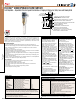
VANE OPERATED FLOW SWITCH
Field Adjustable – Dependable Protection Against Flow Variation or Stopping in Pipelines for Fluids, Gases and Flowing Solids
V4 UNIVERSAL VANE FLOW CHARTS
Values shown in both charts are nominal. If normal ows exceed actuation rates by less than 10%, custom vanes are recommended.
Figures are based on standard vertical installation in a 1-1/2” threaded branch connection in a horizontal run of pipe.
APPROXIMATE ACTUATION/DEACTUATION FLOW RATES FOR COLD WATER; GPM (LPM)
Vane Layers 1.5˝ Pipe 2˝ Pipe 3˝ Pipe 4˝ Pipe 6˝ Pipe 8˝ Pipe 10˝ Pipe 12˝ Pipe 14˝ Pipe 16˝ Pipe 18˝ Pipe 20˝ Pipe
1 7-3
(26.67-11.67)
15-8
(56.7-30)
45-22
(167-83.3)
95-40
(367-150)
210-120
(800-450)
375-175
(1417-667)
600-300
(2267-1133)
900-450
(3400-1700)
1200-600
(4550-2267)
1400-800
(5300-3033)
2000-1000
(7567-3783)
2400-1200
(9083-4550)
1 & 2 7-4
(26.7-15)
23-14
(86.7-53.3)
50-35
(190-132)
130-90
(500-333)
230-150
(867-567)
450-250
(1700-950)
650-350
(2467-1317)
900-500
(3400-1900)
1200-650
(4550-2467)
1450-800
(5483-3033)
1800-1000
(6817-3783)
1, 2 & 3 11-7
(41.7-26.7)
27-19
(102-71.7)
80-60
(300-233)
160-115
(600-433)
300-180
(1133-683)
450-275
(1700-1033)
600-350
(2267-1317)
750-450
(2750-2083)
1000-600
(3783-2267)
1200-700
(4550-2650)
1, 2, 3 & 4 17-12
(65-45)
60-45
(233-167)
120-90
(450-333)
230-150
(867-567)
310-200
(1167-750)
430-280
(1633-1067)
550-360
(2083-1367)
700-450
(2650-1700)
850-550
(3217-2083)
1, 2, 3, 4 & 5 40-30
(152-113)
80-65
(300-250)
135-100
(517-383)
200-140
(750-533)
290-200
(1100-750)
360-250
(1367-950)
460-325
(1733-1233)
575-400
(2183-1517)
Actuation rates are based on cold water at a specic gravity of 1.0.
For uids of different specic gravity, actuation rates may be approximated by dividing the rate shown by the square root of the specic gravity.
APPROXIMATE ACTUATION/DEACTUATION FLOW RATES FOR COLD AIR; SCFM (LPS)
Vane Layers 1.5˝ Pipe 2˝ Pipe 3˝ Pipe 4˝ Pipe 6˝ Pipe 8˝ Pipe 10˝ Pipe 12˝ Pipe 14˝ Pipe 16˝ Pipe 18˝ Pipe 20˝ Pipe
1 32-17
(15-8)
65-32
(30-20)
210-105
(100-50)
400-200
(190-90)
950-475
(450-220)
1550-850
(730-400)
2400-1300
(1100-600)
3450-1900
(1600-900)
4700-2600
(2200-1200)
6400-3500
(3000-1700)
8000-4400
(3800-2100)
10000-5500
(4700-2600)
1 & 2 23-13
(10-6)
120-70
(60-30)
195-140
(90-70)
550-375
(260-180)
1100-700
(520-330)
1850-1200
(870-570)
2700-1750
(1300-800)
3400-2200
(1600-1000)
4800-3100
(2300-1500)
6000-3900
(2800-1800)
7400-4800
(3500-2300)
1, 2 & 3 60-48
(30-20)
135-100
(60-50)
375-265
(180-130)
725-500
(340-240)
1200-850
(570-400)
1850-1300
(870-610)
2600-1800
(1200-800)
3350-2350
(1600-1100)
4300-3000
(2000-1400)
5300-3700
(2500-1700)
1, 2, 3 & 4 65-50
(30-20)
260-200
(120-90)
500-400
(240-190)
875-700
(410-330)
1250-1000
(590-470)
1900-1500
(900-710)
2500-2000
(1200-900)
3100-2500
(1500-1200)
3900-3100
(1800-1500)
1, 2, 3, 4 & 5 130-100
(60-50)
310-250
(150-120)
650-525
(310-250)
1000-800
(470-380)
1600-1250
(760-590)
2200-1750
(1040-830)
2800-2250
(1300-1100)
3550-2850
(1700-1300)
Actuation rates are based on air at standard conditions.
For gases at other pressures, temperatures, or specic gravities, consult factory for equivalent ow approximations.
APPLICATION DRAWINGS
FOR FLOTECT
®
AUTOMATIC FLOW SWITCHES
FLOW
REQUIRED FLOW HOLDS
SWITCH OPEN WHEN FLOW
SLOWS, VANE DROPS,
ACTUATION SWITCH
ALUMINUM ENCLOSURE
FOR ELECTRICAL
CONNECTIONS
SWITCH BODY MACHINED
FROM BAR OF BRASS OR
STAINLESS STEEL
THREADED COVER IS
EASILY REMOVED FOR
ACCESS TO SWITCH
3/4˝ [19.50] NPT OR M25
FOR CONDUIT
1-1/2 [38.10]
THREADED BRANCH
CONNECTION
CUT 1-15/16 [49.21] MIN.
HOLE IN PIPE
FLOW
FLOW
2-1/2 [63.50]
THREDOLET
Ø2-7/8
[73.03]
MINIMUM
HOLE IN
PIPE
FLOW
2-1/2 X 1-1/2
[63.50 X 38.10]
FACE OR HEX
BUSHING
FLOW
1
[25.40]
2-1/16
[52.39]
BORE I.D.
1-1/2 [38.10]
3000 LB
COUPLING
A
FLOW
ANSI RF
THREADED
REDUCING
FLANGE
ANSI RF
WELDING
NECK
FLANGE
*
1-1/2 [38.10]
THREDOLET
Ø1-15/16
[49.21]
MINIMUM
HOLE IN
PIPE
FLOW
Standard installation
1-1/2˝ x 1-1/2˝x 1-1/2˝
(38.10 x 38.10 x 38.10 mm)
tee installation
2-1/2˝ (63.50 mm) threaded
branch connection
Flange installation
*Flange face to pipe O.D.
specied by customer.
Normally should not
exceed 5˝ (172)
2˝ x 2˝ x 2˝
(50.80 x 50.80 x 50.80 mm)
tee installation
Not recommended, unless
coupling is bored out to
2-1/16˝ (52.4) as shown
Pipe Size Dim. A
2˝ (50.80 mm)
3˝ (76.20 mm)
4˝ (101.60 mm)
2-5/8 (66.7)
2-1/2 (63.5)
2-7/16 (61.9)
Threaded branch connection installation.
May also be installed using tee, ange or coupling.
SERIES V4 | W. E. ANDERSON
™
BY DWYER
®
DWYER INSTRUMENTS, INC. | dwyer-inst.com
USA: California Proposition 65
WARNING: Cancer and Reproductive Harm - www.P65Warnings.ca.gov