
Installation Sheet

- 3 -
Before continuing, determine the type of water supply connecation you have from the
chart below and use the appropriate assembly parts required to properly reconnect
the water supply. DO NOT use plumber’s putty to seal these ttings.
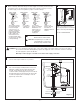
8a
With correct washers in place
(see Step 8a), tighten COUPLING
NUT 1/4 turn beyond hand tight.
DO NOT OVERTIGHTEN.
8b
7302189-100 Rev. A (3/15)
9a
9b
Connect chain clip to middle hole on pull lever.
Turn on water supply and adjust water level to level
indicated on tank by pushing down the inlet valve
lock tab, turning upper body side of inlet valve
counterclockwise, setting upper body of inlet valve at
desired height, then turning upper body of inlet valve
clockwise and pushing the lock tab up to lock the
upper body of inlet valve.
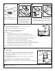
METAL / COPPER
FLARED TUBING
METAL FLANGED
TUBING
METAL SPIRAL
TUBING
VINYL / BRAIDED
CONNECTOR
LOCK NUTLOCK NUT LOCK NUT LOCK NUT
COUPLING
NUT
COUPLING
NUT
EXISTING
COUPLING
NUT
COUPLING
NUT
WATER
SHUT-OFF
WATER
SHUT-OFF
WATER
SHUT-OFF
WATER
SHUT-OFF
CONE
WASHER
EXISTING
CONE
WASHER
EXISTING
WASHER
These parts must be
used as illustrated to
insure water-tight
connection. Use of
existing coupling nut
may result in water
leakage. Water supply
tube or pipe must
extend at least 1/2"
inside threaded shank
of valve (does not apply
to anged tubing).
Use existing
coupling nut
and washer.
Use existing
spiral cone washer.
Fluidmaster cone
washer may not
seal completely
on spiral type
supply line.
Captive cone
washers already
included. No
additional washers
needed.
!
CAUTION: DO NOT USE CONE WASHER
WITH PLASTIC SUPPLY LINE.
!
CAUTION: Overtightening of LOCK NUT or
COUPLING NUT could result in
breakage and potential ooding.
!
WARNING: Do not use plumber’s putty, pipe dope, or any other sealant on the water supply connection to this tank. If
the connection leaks after hand tightening, replace the supply line. If the connection continues to leak with
the new supply line, replace the ll valve.
Warranty is void if any type of sealant is used on the water supply connection.
FLUSH
VALVE
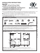
Diagram 1
PARTS FOR WATER
CONNECTION
(SEE STEP 8)
CONE WASHER
THREADED
SHANK
COUPLING NUT
(HAND TIGHT ONLY)
LOCK NUT
INLET
VALVE
LOCK TAB
ADJUST
TO SHOW
NUMBER 8
SLIDE WINDOW
ALL THE
WAY DOWN
UPPER BODY OF
INLET VALVE