
Installation Sheet


- 4 -
M965704 Rev. 1.1 (2/17)
7
8
9
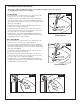
ATTACH CABLE CONNECTOR
CHECK OPERATION OF POP-UP
MAKE WATER SUPPLY AND WASTE CONNECTIONS
• Thread CABLE CONNECTOR (1) clockwise
onto DRAIN BODY CONNECTION (2) and
hand tighten. Fig. A.
• Your new POP-UP DRAIN installation is
now complete. Fig. B.
Note: Tailpeice on pop-up drain is
1-1/4" (32 mm) O.D. Fig. B.
• Operate LIFT KNOB (1) to verify that STOPPER (2) opens and closes.
Note: If STOPPER (2) does not open and close properly then refer to the
“troubleshooting section” of these instructions.
• Connect FLEXIBLE SUPPLIES (1, 2) directly to wall supplies.
Connection on tting supplies are 3/8" (10 mm) compression. Connect
left SUPPLY (1) to Hot (Marked with a Red Band) and right supply
to COLD (2) wall supply.
• Faucet supplies are 24" (610 mm) long from faucet base.
Note: If additional supply length is required, installer must
purchase additional parts separately.
Important: If SUPPLY HOSES (1, 2) are to long, loop as
illustrated to avoid kinking.
• Connect 1-1/4" O.D. (32 mm) tailpiece on POP-UP DRAIN to
waste outlet.
2
1
1-1/4” O.D.
Fig. A. Fig. B.
2
1
24"
(610mm)
1
2
COLD
HOT
3/8" (9.5mm)
COMPRESSION
RED
BAND
BLUE
BAND