
Installation Sheet


- 2 -
M965554 Rev. 1.6 (5/15)
1
2 3
4
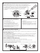
INSTALL DIVERTER INSTALL DIVERTER COVER
AND VALVE COVER
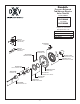
INSTALL TRIM
• When nished tiling the wall, remove PLASTER GUARD (1).
Remove two screws that secure the DIVERTER LID (2) and
remove Lid. Inspect the inside surface of diverter port.
Diverter port must be free of any dirt. Clean if necessary.
• Install DIVERTER (3) with SCREWS (4) removed
from DIVERTER LID (2).
• Operate DIVERTER (3). DIVERTER (3) should slide
in and out smoothly.
• Push CAP (1) over VALVE CARTRIDGE (2) until
seated against stop. Push CAP (3) over
DIVERTER (4) until seated against stop.
NOTE: When soldering, remove PLASTER GUARD, CARTRIDGES and CHECK STOPS (IF PRESENT).
When finished soldering, flush valve body, replace cartridges, check stops (if present) and plaster
guard to continue installation. Use thread sealant or Teflon tape on threaded connections.
• See Roughing-in diagram before starting.
Connections are:
— 1/2" (13 mm) female NPT for threaded inlets
• Connect RISER PIPE
(1)
to MANIFOLD
(2)
top outlet marked “SHR”.
• Connect TUB FILLER PIPE
(3)
at bottom outlet marked “TUB”.
• For proper positioning the nished wall must be within side wall of PLASTER GUARD
(4)
.
• If the valve is installed on a berglass or other thin wall application, the PLASTER GUARD (4)
can be used as a support.
— Cut a 4" (102 mm) dia. hole in the shower stall.
— Drill two additional 1" (25 mm) holes to allow access to the stops.
— Remove PLASTER GUARD (4), rotate 180˚ so that indicated screw holes t.
— MANIFOLD (2). Push CAP on valve, place ESCUTCHEON on and attach with screws.
• Connect hot and cold water supplies.
• Cap off shower pipe (5) and tub ller pipe (6).
• For support, use pipe BRACES (7) secured to wooden braces.
• With valve turned off, turn on water supplies. Check for leaks.
ROUGHING-IN
CAUTION
Turn off hot and cold water
supplies before beginning.
CAUTION
Turn off hot and cold water
supplies before beginning.
COLD
HOT
1
7
5
3
6
4
2
GREASE
O-RING
6
7
3
11
13
12
1
10
5
4
9
PIPE CAP
14
8
2
1
2
4
3
DIVERTER
PORT
1
2
3
4
• Push CAP (1) onto VALVE CARTRIDGE (2). Mount ESCUTCHEON HOLDER (3) with gasket
and the ESCUTCHEON (4) to valve body and secure with SCREWS (5).
• Push the COVER (6) as shown over the CAP (1).
• Push ADAPTER (7) over CARTRIDGE STEM (8). Push ESCUTCHEON (9)
onto ADAPTER (7). Mount CROSS HANDLE (10) or LEVER HANDLE (11)
and secure with WASHER and SCREW (12).
• Thread DIVERTER KNOB (14) onto diverter stem.