
Installation Sheet

- 2 -
M965816 Rev. 1.0 (7/17)
2
3
1
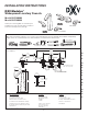
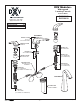
TEE ASSEMBLY
INSTALL VALVE BODIES
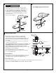
• Insert SPOUT (1) through center hole, making sure SEAL
WASHER (2) is properly seated in SPOUT BASE (3) groove.
• Assemble RUBBER WASHER (4), BRASS WASHER (5) and
LOCKNUT (6) onto SPOUT SHANK (7) from under side
of sink. Make sure SPOUT (1) is centered in the mounting
hole and the slot in the BRASS WASHER (5) faces toward
the front of the sink.
• Tighten LOCKNUT (6) rmly.
SPOUT ASSEMBLY
CAUTION
Turn off hot and cold water
supplies before beginning.
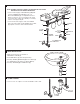
• Thread TEE BODY (1) COUPLING NUT (2) to
SPOUT SHANK (3). Tighten with wrenches.
• Unpack valve assembly and Modulusove HANDLE (9).
Unthread FLANGE (8) removing from VALVE BODY (2).
• Thread LOCKNUT (1) to bottom of VALVE BODY (2). Make sure
SPACER (3), BRASS WASHER (4) and RUBBER WASHER (5)
are installed.
• Insert VALVE BODY (2) through mounting hole from underside
of lavatory or mounting surface.
Note: VALVE BODY marked Hot is installed in the left Mtg. hole,
VALVE BODY marked Cold in the right when facing front of
fitting. Maximum mounting surface thickness is 1-3/4".
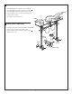
• Install STOP RING (6) onto VALVE BODY (2) if not in place. Install
WASHER (7) beneath FLANGE (8).
• Thread FLANGE (8) ush against STOP RING (6).
• Align VALVE BODY (2) and from below tighten LOCKNUT (1)
to secure VALVE BODY (2).
INSTALL HANDELS
• Turn VALVES to off position. Align HANDLES (9) as shown or as
desired and install onto CARTRIDGE STEM (10). Make sure the
O-ring (14) is properly seated in the handle base groove.
HOSE CONNECTIONS
• Tighten COUPLING NUT (11) on SUPPLY HOSE (13) to OUTLET (12) making water tight connection.
Important: Loop SUPPLY HOSES (13) as shown so they do not kink.
4
6
5
SLOT
2
7
3
1
1-3/8'' (35mm) MAX.
STOP RING
14
1
2
HOT
12
5
11
COLD
13
11
3
4
8
6
10
7
9
1
3
2