
Installation Guide


13
INSTALLATION
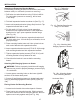
MAN AUTO
Fan Switch
Thermo-switch
Fan
White
Black
Green
110/115
VAC
Wiring Diagram
Fig. 12- Fan Wiring Diagram
MAN AUTO
Fig. 11 - Operating Fan
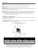
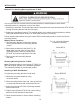
LOCATING HEATER
This heater is designed to be mounted on a wall or on
a oor, using the Support Legs (Select Models) includ-
ed with select models.
For convenience and efciency, install heater:
1. Where there is easy access for operation,
inspection, and service.
2. In the coldest part of room.
3. A minimum of 3' away from furniture and draperies.
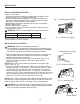
FLOOR MOUNTING (Select Models)
(Cannot be done in bedroom or bathroom)
(Cannot be used for garage and ice-house heaters)
NOTE: This is an optional accessory and is not
required for operation of the heater.
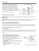
Before installing Support Legs to heater base, please
make sure you have the following items:
(2) Support Legs
(4) Support Leg Screws (M4*15)
1. Set down a blanket onto the table where the heater
will be placed for leg installation to prevent scratch-
ing of the table and/or the heater.
2. Set back of heater on table with the bottom of heater
extending outside the table edge.
3. Fasten Support Legs to heater using Support Leg
Screws (Fig.13)
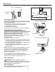
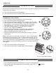
Note: If the heater is to be installed directly on carpet-
ing, tile or other combustible material, other than
wood ooring, the appliance shall be installed on a
metal or wood panel extending the full width and
depth of the appliance.
3. Once positioned, secure heater to the oor
using Support Leg Screws (M4*15) and mounting holes
found on heater Support Legs (See Fig. 14).
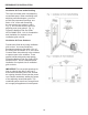
WALL MOUNTING
WARNING: Failure to position the parts in
accordance with these diagrams or failure to use only
parts specically approved with this heater may result in
property damage or personal injury.
Mounting Bracket
The mounting bracket is located separately from the
unit, but packed inside the same box.
Support Leg
Fig. 14 - Securing Support Leg
Fan Rocker
Switch
Rocker Switch
Fig. 13 - Attaching Legs
Support Leg
Screw
Support Leg