5-BURNER NATURAL GAS BARBECUE Model #DGA550SSN/ DGA550SSN-D Français p. 30 Español p. 59 ANS Z21.58b-2012 CSA 1.6b-2012 Outdoor Cooking Gas Appliance ATTACH YOUR RECEIPT HERE Serial Number Purchase Date Questions, problems, missing parts? Before returning to your retailer, call our customer service department at 1-877-447-4768, 8:30 a.m. – 4:30 p.m., CST, Monday – Friday, or e-mail us at customerservice@ghpgroupinc.com.
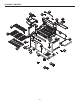
PACKAGE CONTENTS Q U V O P T S D W F G Y M L X E N I J R A1 H Z K A B C 3
PACKAGE CONTENTS PART A B C D E F G H I J K L M N DESCRIPTION QUANTITY Bottom Shelf 1 Locking Caster 2 Caster 2 Cart Left Side Panel 1 Cart Right Side Panel 1 Cart Rear Panel 1 Upper Front Door Brace 1 Left Door Assembly 1 Right Door Assembly 1 Door Handle 2 Door Handle Sleeve 4 AA Battery 1 Main Burner Control Knob 5 (Lg) Side/Rear Burner Control 2 Knob (Sm) PART DESCRIPTION QUANTITY O Grill Body 1 P Left Shelf 1 Q Side Burner Cooking 1 Grate R Right Shelf 1 S Grease Pan 1 T Grease Cup 1 U Lid Handle 1 V
HARDWARE CONTENTS (shown actual size) AA BB CC DD M6x12 Screw Qty. 29 Plain Washer Qty. 16 Spring Washer Qty. 16 M4x10 Screw Qty. 14 FF GG M6x16 Screw Qty. 10 M4x10 Screw Qty. 4 HH NOTE: Four screws preassembled with bottom shelf. EE M6x20 Screw Qty. 4 M6x25 Screw Qty. 2 NOTE: Preassembled with door handle. NOTE: Preassembled with lid handle. SAFETY INFORMATION Please read and understand this entire manual before attempting to assemble, operate or install the product.
SAFETY INFORMATION CAUTION • NEVER use charcoal or lighter fluid with the grill. • DO NOT use gasoline, kerosene or alcohol for lighting. • This grill is not intended to be used in or installed on recreational vehicles and/or boats. •A LWAYS open grill lid slowly and carefully as heat and steam trapped within the grill can burn you severely. • NEVER attempt to operate this grill using propane.
SAFETY INFORMATION •D O NOT touch metal parts of grill until it has completely cooled (about 45 minutes) to avoid burns, unless you are wearing protective gear (pot holders, gloves, BBQ mittens, etc…). • DO NOT alter this grill in any manner. • Clean and inspect the hose before each use. If there is evidence of abrasion, wear, cuts, or leaks, the hose must be replaced prior to operating the appliance.
AA CC BB AA DD CC BB EE AA DD CC BB EE DD CC EE DD 1. A ttach two locking casters (B) to the rear of the bottom shelf (A) and secure using four plain washers (BB), four spring washers (CC), and four M6x12 screws (AA) for each locking caster (B). Hardware Used M6x12 Screw BB Plain washer CC Spring washer 2. A ttach two casters (C) to the front of the bottom shelf (A) and secure using four plain washers (BB), four spring washers (CC), and four M6x12 screws (AA) for each caster (C).
NOTE Preassem with lid ha 4 9 Spring Washer Qty. 16 1 1 NOTE: Preassembled with door handle. Plain Washer Qty. 16 M6x25 Screw Qty. 2 GG NOTE: Preassembled with lid handle. M4x10 Screw Qty. 4 FF Plain Washer Qty. 16 2 E 1 F 1 A AA 1 E NOTE: Preassembled with door handle. HH D 2 AA Spring Washer Qty. 16 1 GG M4x10 Screw Qty. 12 x3 E D 6 FF M6x12 Screw AA AA 1 2 M6x12 Screw Qty. 40 BB 6.
Plain Washer Qty. 16 NOTE: Preassembled with door handle. GG 1 M4x10 Screw Qty. 4 M6x12 Screw 7 AA D 1 E M6x25 Screw Qty. 2 FF NOTE: Preassembled with lid handle. AA EE AA Hardware Used M6x12 Screw Qty. 40 BB 7. Partially insert two M6x12 screws (AA) into the cart left and right side panels (D & E). Attach upper front door brace (G) to the four M6x12 screws (AA). Tighten the screws. Spring Qt M6x2 Qt M4x10 Screw Qty. 12 ASSEMBLY INSTRUCTIONS x4 G 2 3 M6x16 Screw Qty.
ASSEMBLY INSTRUCTIONS 10. R emove preassembled M6x25 screws (HH) from the lid handle (U). Attach the lid handle (U) by inserting two M6x25 screws (HH) from inside the lid of the grill body (O), through the lid handle bezels (V), into the lid handle (U) and tightening securely. HH O 11 HH Spring Washer Qty. 16 O 11 O M NOTE: Preassembled with door handle. FF OTE: Make sure the natural gas hose is inside N the cart and exits through the opening hole in the cart rear panel (F).
M6x16 Screw Qty. 10 13 Spring Washer Qty. 16 NOTE: Preassembled with lid handle. M4x10 Screw Plain Washer Qty. 4 Qty. 16 Spring Washer Qty. 16 NOTE: Preassembled with door handle. Qty. 4 FF HH 2 15 1 NOTE: Preassembled with door handle. M4x10 Screw Qty. 4 Plain Washer Qty. 16 GG NOTE: FF Preassembled with lid handle. DD 1 O G 12 FF Spring Washer Qty. 16 HH x2 M6x20 Screw Qty. 4 M6x16 Screw Qty. 10 Screw . 12 CC M6x16 Screw B FF DD Hardware Used 1 2 15.
M6x12 Screw M4x10 Screw M6x16 Screw M6x12 Screw M4x10 Screw M6x16 Screw Qty. 40 Qty. 12 Qty. 40 Qty. 12 Qty. 10 Qty. 10 M6x20 Screw M6x20 Screw M6x25 Screw M6x25 Screw Qty. 4 Qty. 4 Qty. 2 Qty. 2 GG FF HH GG FF HH NOTE: NOTE: Preassembled Preassembled with lid handle. with lid handle. ASSEMBLY INSTRUCTIONS AA 1 O 2 17 x2 DD AA FF 18 18. Attach the ignition wiring to the electrode. 13 2 2 NOTE: NOTE: Preassembled Preassembled with door handle. with door handle.
ASSEMBLY INSTRUCTIONS 19 19. Align the key holes on the burner tray with the side burner cooking grate (Q) and set in place. NOTE: Preassembled with lid handle. 1 er 2 FF R 1 NOTE: Preassembled with door handle. Spring Washer Qty. 16 1 Plain Washer Qty. 16 Spring WasherM4x10 Screw Qty. 16 Qty. 4 HH FF 2 14 w 21 x3 M6x20 Screw Qty. 4 M6x12 Screw M6x16 Screw M4x10 Screw Qty. 40 10 Qty. 12 Qty. BBEE AADD M6x16 Screw CC FF GG NOTE: Preassembled with lid handle. M6x20 Screw Qty.
ASSEMBLY INSTRUCTIONS WARNING: IT IS VERY IMPORTANT TO CHECK AND ENSURE THAT EACH AND EVERY BURNER IS FULLY ENGAGED WITH THE ADJACENT VALVE ORIFICE BEFORE COMPLETING STEP 22. FAILURE TO DO SO MAY RESULT IN FIRE OR EXPLOSION, POSSIBLY CAUSING SERIOUS INJURY OR DEATH. REFER TO MAINTENANCE SECTION INSTRUCTIONS TO PROPERLY CHECK THE ENGAGEMENT. WARNING Burner Valve Orifice 22 22. Open the lid of the grill body (O) and place the five heat tents (X) on the brackets directly above the burners.
ASSEMBLY INSTRUCTIONS 24 24. Insert the warming rack (W) into the two holes located on the back edge of the grill body (O). W 25 1 O 2 1 25. Insert the grease pan (S) into position by sliding it in the grill body (O) from the rear along the rails. Insert the grease cup (T) into position by sliding it onto the rails located on the bottom side of the grease pan (S). T S 26. Remove the igniter cap by turning it counterclockwise.
BARBECUE AU GAZ NATUREL À CINQ BRÛLEURS MODÈLE #DGA550SSN/ DGA550SSN-D ANS Z21.58b-2012 CSA 1.6b-2012 Appareil de cuisson au gaz extérieur JOIGNEZ VOTRE REÇU ICI Numéro de série Date d’achat Des questions, des problèmes, des pièces manquantes? Avant de retourner l’article au détaillant, appelez notre service à la clientèle au 1-877-447-4768, 08:30-16 heures 30, HNC, du lundi - vendredi ou par e-mail à customerservice@ghpgroupinc.com.
CONTENU DE L’EMBALLAGE Q U V O P T S D W F G Y M L X E N I J R A1 H Z K A B C 32
CONTENU DE L’EMBALLAGE PIÈCE A B C D E F G H I J K L M DESCRIPTION Tablette inférieure Roulette avec frein Roulette Panneau latéral gauche du chariot Panneau latéral droit du chariot Panneau arrière du chariot Traverse supérieure de la porte Ensemble de porte gauche Ensemble de porte droite Poignée de porte Manchon de la poignée de porte Pile AA Bouton de commande de brûleur principal QUANTITÉ 1 2 2 1 PIÈCE DESCRIPTION N Bouton de commande du brûleur latéral et du brûleur arrière O Corps du barbecue P T
QUINCAILLERIE INCLUSE (grandeur réelle) AA BB CC DD Boulon M6x12 Rondelle ordinaire Rondelle à ressort Boulon M4x10 Qté : 14 Qté : 16 Qté : 16 Qté : 29 FF GG Boulon M6x16 Qté : 10 Boulon M4x10 Qté : 4 REMARQUE : Préassemblés à la poignée de porte. CONSIGNES DE SÉCURITÉ HH REMARQUE : Quatre vis sont préassemblés dans la tablette inférieure. EE Boulon M6x20 Qté : 4 Boulon M6x25 Qté : 2 REMARQUE : Préassemblés à la poignée du couvercle.
CONSIGNES DE SÉCURITÉ MISE EN GARDE • N’utilisez jamais de charbon de bois ni d’essence à briquet avec ce barbecue. • N’utilisez pas d’essence, de kérosène ou d’alcool pour l’allumage. • Ce barbecue n’est pas destiné à être utilisé ou installé sur un véhicule récréatif ou un bateau. • Ouvrez toujours le couvercle du barbecue lentement et avec précaution, car la chaleur et la vapeur emprisonnées qui s’en échappent peuvent causer des brûlures graves.
CONSIGNES DE SÉCURITÉ •N e touchez pas les éléments en métal du barbecue avant que celui-ci ne soit complètement refroidi (environ 45 minutes) afin d’éviter les brûlures, à moins d’utiliser des articles de protection (poignées, gants, mitaines pour le barbecue, etc.). • Ne modifiez ce barbecue d’aucune façon. • Nettoyez et inspectez le tuyau avant chaque utilisation.
CC BB AA DD AA AA CC BBEE AA DD DD Boulon M6x12 BB EE CC CC Quincaillerie utilisée BB Rondelle ordinaire CC Rondelle à ressort 2. Fixez deux roulettes (C) à la partie avant de la tablette inférieure (A) à l’aide de quatre rondelles ordinaires (BB), quatre rondelles à ressort (CC) et quatre vis M6 de 12 mm (AA) pour chaque roulette avec frein (C). Quincaillerie utilisée Boulon M6x12 BB Rondelle ordinaire CC Rondelle à ressort 3. Retournez la tablette inférieure (A).
4 D HH 1 Spring Washer Qty. 16 2 Plain Washer Qty. 16 HH GG M4x10 Screw Qty. 12 6 2 x3 38 2 NOTE: Preassembled with door handle. M4x10 Screw Qty. 4 1 AA E 1 F 1 A 1 E AA M4x10 Screw Qty. 4 Boulon M6x12 1 D D FF AA AA Quincaillerie utilisée M6x12 Screw Qty. 40 BB 6. P our fixer le panneau arrière du chariot (F), glissez les encoches en trou de serrure de ce dernier sous les vis (AA) précédemment insérées.
D NOTE: Preassembled with door handle. 2 3 1 1 J Spring Washer Qty. 16 8 H GG Plain Washer Qty. 16 K M4x10 Screw Spring Washer Qty. Qty. 16 4 9 D 1 2 NOTE: Preassembled with door handle. x4 DD Plain Washer Qty. 16 2 NOTE: reassembled th door handle. 39 FF H 4x10 Screw Qty. 4 GG M4x10 Screw Qty. 12 1 x8 6x12 Screw Qty. 40 CC AA BB Boulon M4x10 AA DD Plain Washer Qty. 16 2 9.
INSTRUCTIONS POUR L’ASSEMBLAGE 10. R etirez les vis M6 de 25 mm préassemblées (HH) de la poignée du couvercle (U). Pour fixer la poignée du couvercle (U), insérez deux vis M6 de 25 mm (HH), à partir de l’intérieur du couvercle du corps barbecue (O), dans les collerettes de la poignée du couvercle (V), puis dans la poignée (U). Serrez fermement. 1 1 M6x16 Screw Qty. 10 O 11 HH Spring Washer Qty. 16 O 40 M NOTE: Preassembled with door handle. O M4x10 Screw Qty.
M6x16 Screw Qty. 10 13 Spring Washer Qty. 16 M4x10 Screw Plain Washer Qty. 4 Qty. 16 Spring Washer Qty. 16 NOTE: Preassembled with door handle. NOTE: Preassembled with lid handle. HH 1 41 2 1 Plain Washer Qty. 16 1 O NOTE: Preassembled with door handle. 15 M4x10 Screw Qty. 4 2 DD FF Spring Washer Qty. 16 x2 M6x20 Screw Qty. 4 DD Boulon M6x16 CC FF crew 2 EE AA 15. I nsérez partiellement deux vis M6 de 16 mm (FF) dans le côté gauche du corps du barbecue (O).
INSTRUCTIONS POUR L’ASSEMBLAGE CC CC BB BB Boulon M4x10 AA AA 18. Fixez le fil d’allumage à l’électrode. O 2 17 x2 DD 18 42 1 2 2 1 DD FF x3 17. Alignez le tube du brûleur latéral avec l’orifice du brûleur latéral, puis insérez-le dans l’orifice du brûleur latéral. Fixez l’orifice du brûleur latéral et son support au support du brûleur latéral à l’aide de deux vis M4 de 10 mm (DD). Quincaillerie utilisée 1 NOTE: NOTE: Preassembled Preassembled handle. withwith doordoor handle.
INSTRUCTIONS POUR L’ASSEMBLAGE 19 19. Alignez les encoches en trou de serrure du plateau du brûleur avec la grille de cuisson du brûleur latéral (Q), puis fixez cette dernière en place. 1 O 43 2 2 FF R 1 NOTE: Preassembled with door handle. Plain Washer Qty. 16 Spring Washer Qty. 16 1 FF x3 Spring WasherM4x10 Screw Qty. 16 Qty. 4 HH GG NOTE: Preassembled with lid handle. 21 HH AADD Boulon M6x16 CC FF M6x20 Screw Qty. 4 Quincaillerie utilisée M6x12 Screw M6x16 Screw M4x10 Screw Qty.
INSTRUCTIONS POUR L’ASSEMBLAGE AVERTISSEMENT : IL EST TRÈS IMPORTANT DE S’ASSURER QUE CHACUN DES BRÛLEURS EST COMPLÈTEMENT INSÉRÉ DANS L’ORIFICE DU ROBINET ADJACENT AVANT DE PASSER À L’ÉTAPE 22. LE NON-RESPECT DE CETTE CONSIGNE POURRAIT ENTRAÎNER UN INCENDIE OU UNE EXPLOSION, CE QUI POURRAIT CAUSER DES BLESSURES GRAVES, VOIRE LA MORT. CONSULTEZ LES INSTRUCTIONS DE LA SECTION ENTRETIEN INDIQUANT LA FAÇON ADÉQUATE DE VÉRIFIER SI LES BRÛLEURS SONT INSÉRÉS. 22.
INSTRUCTIONS POUR L’ASSEMBLAGE 24. Insérez la grille de maintien au chaud (W) dans les deux trous situés sur le rebord arrière du corps du barbecue (O). 24 W 25 1 O 2 1 25. Pour insérer le bac ramasse-graisse (S), glissezle dans le corps du barbecue (O) à partir de l’arrière, le long des rails. Pour mettre en place le gobelet ramasse-graisse (T), glissez-le sur les rails situés sur l’extrémité inférieure du bac ramasse-graisse (S). T S 26.
PARRILLA A GAS NATURAL DE 5 QUEMADORES MODELO # DGA550SSN/ DGA550SSN-D ANS Z21.58b-2012 CSA 1.6b-2012 Electrodoméstico a gas para cocinar en exteriores ADJUNTE SU RECIBO AQUÍ Número de serie Fecha de compra ¿Preguntas, problemas, piezas faltantes? Antes de volver a la tienda, llame a nuestro Departamento de Servicio al Cliente al 1-877-447-4768, de 8:30 am - 4:30 pm, hora central, de lunes - viernes o envíe un correo electrónico a customerservice@ghpgroupinc.com.
CONTENIDO DEL PAQUETE Q U V O P T S D W F G Y M L X E N I J R A1 H Z K A B C 61
CONTENIDO DEL PAQUETE PIEZA A B C D E F G H I J K L M DESCRIPCIÓN CANTIDAD Repisa inferior 1 Rueda con seguro 2 Rueda 2 Panel lateral izquierdo del 1 carrito Panel lateral derecho del 1 carrito Panel posterior del carrito 1 Abrazadera de la puerta 1 superior Ensamble de la puerta 1 izquierda Ensamble de la puerta 1 derecha Manija de la puerta 2 Manguito de la manija de 4 la puerta Batería AA 1 Perilla de control del 5 quemador principal PIEZA DESCRIPCIÓN CANTIDAD N Perilla de control del 2 quemador later
ADITAMENTOS (se muestran en tamaño real) AA Perno M6x12 Cant. 29 CC BB DD Arandela lisa Arandela de resorte Cant. 16 Cant. 16 FF GG Perno M6x16 Cant. 10 Perno M4x10 Cant. 4 NOTA: Preensamblados con la manija de la puerta. INFORMACIÓN DE SEGURIDAD Perno M4x10 Cant. 14 HH NOTA: Cuatro tornillos preensamblados con estante inferior. EE Perno M6x20 Cant. 4 Perno M6x25 Cant. 2 NOTA: Preensamblado con la manija de la tapa.
INFORMACIÓN DE SEGURIDAD PRECAUCIÓN • Nunca utilice carbón o líquido para encendedor en la parrilla. •N o use gasolina, queroseno ni alcohol para encender la parrilla. • Esta parrilla no está diseñada para usarse o instalarse en vehículos recreativos y/o botes. • SIEMPRE abra la tapa de la parrilla lentamente y con cuidado, ya que el calor y el vapor atrapados dentro de la parrilla pueden causar quemaduras graves. • NUNCA intente operar esta parrilla con propano.
INFORMACIÓN DE SEGURIDAD •N O toque las piezas metálicas de la parrilla hasta que se hayan enfriado completamente (espere unos 45 minutos) para evitar quemaduras, a menos que utilice artículos de protección (almohadillas, guantes, manoplas para horno, etc.). • NO altere la parrilla de ninguna manera. • Limpie e inspeccione la manguera antes de cada uso. Si hay evidencia de abrasión, desgaste, cortes o fugas, debe reemplazar la manguera antes de hacer funcionar el electrodoméstico.
AA CC BB AA DD CC BB EE AA DD CC BB EE DD CC Aditamentos utilizados AA Perno M6x12 BB Arandela lisa CC Arandela de resorte 2. F ije dos ruedas con (C) a la parte frontal de la repisa inferior (A) y fije con cuatro arandelas lisas (BB), cuatro arandelas de resorte (CC) y cuatro tornillos M6X12 (AA) para cada rueda (C). Aditamentos utilizados AA Perno M6x12 BB Arandela lisa CC Arandela de resorte 3. I nserte parcialmente cuatro tornillos M6x12 (AA) en la repisa inferior (A).
1 67 1 2 NOTE: Preassembled with door handle. AA E 1 F 1 A AA 1 E NOTE: Preassembled with door handle. M4x10 Screw Qty. 4 2 Plain Washer Qty. 16 GG D M4x10 Screw Qty. 4 HH Spring Washer Qty. 16 FF 1 6 FF 1 D 2 x3 E Plain Washer Qty. 16 A Spring Washer Qty. 16 1 HH M6x20 Screw Qty. 4 M4x10 Screw Qty. 12 M6x12 Screw Qty. 40 BB Perno M6x12 AA AA 2 AA M6x25 Screw Qty. 2 GG NOTE: Preassembled with lid handle. x2 6.
1 J Spring Washer Qty. 16 1 NOTE: Preassembled with door handle. 2 3 H GG Plain Washer Qty. 16 K M4x10 Screw Spring Washer Qty. Qty. 16 4 9 D 1 2 NOTE: Preassembled with door handle. x4 DD Plain Washer Qty. 16 2 NOTE: reassembled th door handle. 68 FF H 4x10 Screw Qty. 4 GG M4x10 Screw Qty. 12 1 x8 6x12 Screw Qty. 40 CC AA BB Perno M4x10 AA DD D 8 9.
INSTRUCCIONES DE ENSAMBLAJE 10. R etire los tornillos preensamblados (HH) de la manija de la tapa (U). Fije la manija de la tapa (U) insertando dos tornillos M6x25 (HH) desde el interior de la tapa del cuerpo de la parrilla (O), a través de los biseles de la manija de la tapa (V), en la manija de la tapa (U) y apriete bien. HH O 11 HH Spring Washer Qty. 16 O O M NOTE: Preassembled with door handle. FF 12 M4x10 Screw Qty. 4 Plain Washer Qty. 16 N 12.
M6x16 Screw Qty. 10 13 Spring Washer Qty. 16 NOTE: Preassembled with lid handle. M4x10 Screw Plain Washer Qty. 4 Qty. 16 Spring Washer Qty. 16 NOTE: Preassembled with door handle. HH 1 NOTE: Preassembled with door handle. 1 M4x10 Screw Qty. 4 15 Plain Washer Qty. 16 GG NOTE: FF Preassembled with lid handle. 2 DD FF Spring Washer Qty. 16 x2 70 2 Z O M6x20 Screw Qty. 4 M6x16 Screw Qty. 10 DD Perno M6x16 CC FF crew 2 EE AA 15.
INSTRUCCIONES DE ENSAMBLAJE FF 17 DD 18 18. Fije el cable de encendido al electrodo. 71 2 2 2 NOTE: NOTE: Preassembled Preassembled with door handle. with door handle. x2 1 O M4x10 Screw Plain Washer Spring Washer M4x10 Screw Plain Washer Spring Washer Qty. 4 Qty. 16 Qty. 4 Qty. 16 Qty. 16 Qty. 16 CC CC BB BB AA AA Perno M4x10 1 1 DD P x3 17. Alinee los tubos del quemador lateral con el orificio del quemador lateral e inserte los tubos en el orificio.
INSTRUCCIONES DE ENSAMBLAJE 19 19. Alinee los orificios guía en la bandeja del quemador con la rejilla de cocción del quemador lateral (Q) y fije en su lugar. 1 1 2 FF R 1 NOTE: Preassembled with door handle. Spring Washer Qty. 16 Plain Washer Qty. 16 Spring Washer M4x10 Screw Qty. 16 Qty. 4 FF 72 2 er HH NOTE: Preassembled with lid handle. GG 21 x3 Qty. 4 M6x12 ScrewScrew M4x10 Screw M6x16 Qty. 40 Qty. 12 Qty. 10 M6x20 Screw w EE BB AA DD Perno M6x16 CC FF O x2 21.
INSTRUCCIONES DE ENSAMBLAJE ADVERTENCIA: ES MUY IMPORTANTE VERIFICAR Y ASEGURARSE DE QUE TODOS LOS QUEMADORES ESTÉN COMPLETAMENTE ACOPLADOS CON EL ORIFICIO DE LA VÁLVULA ADYACENTE ANTES DE FINALIZAR EL PASO 24. NO HACERLO PODRÍA PROVOCAR UN INCENDIO O UNA EXPLOSIÓN, LO QUE POSIBLEMENTE CAUSARÍA LESIONES GRAVES O LA MUERTE. CONSULTE LAS INSTRUCCIONES DE MANTENIMIENTO PARA VERIFICAR ADECUADAMENTE EL ACOPLAMIENTO. ADVERTENCIA Quemador Orificio de la válvula 22 22.
INSTRUCCIONES DE ENSAMBLAJE 24 24. Introduzca la rejilla para calentar (W) en los dos orificios ubicados en el borde posterior del cuerpo de la parrilla (O). W 25 O 2 1 1 25. Inserte la bandeja de recolección de grasa (S) en su posición, deslizándola en el cuerpo de la parrilla (O) desde la parte posterior a lo largo de los rieles. Inserte el recipiente para grasa (T) en posición deslizándolo sobre los rieles ubicados en la parte inferior del recipiente para grasa (S). T S 26.