3-Burner LP Gas Grill Model #DGB390SNP-D Français p. 28 XX Francais Español p. p. 55 XX Español ANS Z21.58b- 2012 CSA 1.6b- 2012 Outdoor Cooking Gas Appliance ATTACH YOUR RECEIPT HERE Serial Number _____________________________ Purchase Date ______________________ Questions, problems, missing parts? Before returning to your retailer, call our customer service department at 1-877-447-4768, 8:30 a.m. – 4:30 p.m., CST, Monday – Friday or e-mail us at customerservice@ghpgroupinc.com.
TABLE OF CONTENTS Safety Information ...................................................................................................................... 3 Package Contents ...................................................................................................................... 5 Hardware Contents .................................................................................................................... 6 Preparation ...................................................................
SAFETY INFORMATION Please read and understand this entire manual before attempting to assemble, operate or install the product. If you have any questions regarding the product, please call customer service at: 1-877-447-4768, 8:30 a.m. – 4:30 p.m., CST, Monday – Friday. DANGER • Do not use in an explosive atmosphere. Keep grill area clear and free from combustible materials, gasoline and other flammable vapors and liquids.
SAFETY INFORMATION WARNING • Do not place the grill under overhead combustible construction or awnings. Minimum clearance from sides and back of unit to combustible construction, 36 inches (914.4mm) from sides and back. 36in 36in 914.4mm 914.4mm NOTE: The installation must conform with local codes or, in the absence of local codes, with either the National Fuel Gas Code, ANSI Z223.1/NFPA 54, Natural Gas and Propane Installation Code, CSA B149.1, or Propane Storage and Handling Code, B149.2.
PACKAGE CONTENTS R M S T U Q P O J V K E N H I F G L B A D C PART A B C D E F G H I J K DESCRIPTION Bottom Shelf Caster Swivel Caster Locking Swivel Caster Cart Left Side Panel Cart Right Side Panel Cart Rear Panel Upper Front Door Brace Door Handle Door Handle Bezel Door Handle Sleeve QUANTITY PART 1 2 1 1 1 1 1 1 1 2 2 L M N O P Q R S T U V 5 DESCRIPTION Door Assembly Grill Body Side Table Hose Holder Grease Pan Grease Cup Warming Rack Cooking Grate Heat Tent Side Table Support AA Bat
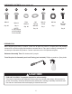
HARDWARE CONTENTS (shown actual size) AA AA BB CC M6x12 M6x12 Qty. 40 Qty. 2 Plain Washer M6 Spring Washer NOTE: 2 (AA) screws preassembled in door handle. Qty. 20 Qty. 16 DDI M4x12 Screw Qty. 1 EE M4 Nut Qty. 1 FF M6 Shoulder Screw Qty. 8 PREPARATION Before beginning assembly of product, make sure all parts are present. Compare parts with package contents list on previous page and hardware contents above. If any part is missing or damaged, do not attempt to assemble the product.
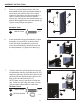
ASSEMBLY INSTRUCTIONS 1. Assemble the casters, including 2 direction casters (B), 1 non-locking swivel caster (C), 1 locking swivel caster (D), onto bottom shelf (A) with 4 M6 screw (AA), plain washer (BB) and spring washer (CC). 1 A B AA C D CC BB Hardware Used 2. AA M6x12 Screw x 16 BB Plain Washer x 16 CC Spring Washer x 16 Insert 4 screws (AA) into holes in bottom shelf (A), leaving 4-6mm clearance from screw head to bottom shelf (A).
ASSEMBLY INSTRUCTIONS 3. Insert one screw (AA) into each of the rear holes of the cart left side panel and cart right side panel (E & F), leaving 4-6mm clearance from screw head to the side panels (E & F). Attached the cart rear panel (G) by sliding the keyholes in the cart rear panel over the inserted screws and then push with force. Secure the cart rear panel (G) to the bottom shelf (A) with 2 screws (AA). Tighten the 2 screws on the side panels (E & F). 3 G E AA Hardware Used AA 4.
ASSEMBLY INSTRUCTIONS 5. Remove 2 preassembled screws (AA) and door handle sleeves (K) from the door handle (I). Insert the 2 door sleeves (K) into the holes located on the back of the door assembly (L), insert 2 screws (AA) into the door handle sleeves (K), through the door handle bezels (J) and into the threaded holes in the door handle (I). Tighten using Phillips screwdriver. 5 J AA I K Hardware Used AA 6.
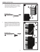
ASSEMBLY INSTRUCTIONS 8. Install side table supports (U) with 2 M6x12mm (AA) screws into holes (labeled 1) in side of grill body (M) and tighten the screws. Repeat with other side table supports (U). 8 M U Hardware Used AA M6x12 Screw x8 1 AA 9. Secure 2 shoulder screws (FF) into holes (labeled 1) of side table supports (U). Secure side table (N) onto side table support (U) by tightening 2 shoulder screws (FF) into holes (labeled 2). Repeat step with the other side table.
ASSEMBLY INSTRUCTIONS 10. Secure gas hose and hose holder (O) assembly onto cart left side assembly (E) by tightening 1 M4*12 screw (DD) and 1 M4 nut (EE) into hole (labeled 1) into cart left side table. NOTE: The gas holder (O) must completely circle the gas hose before securing onto cart left side panel (E) as illustrated below. 10 1 DD O Hardware Used 11.
ASSEMBLY INSTRUCTIONS WARNING: IT IS VERY IMPORTANT TO CHECK AND ENSURE THAT EACH AND EVERY BURNER IS FULLY ENGAGED WITH THE ADJACENT VALVE ORIFICE BEFORE COMPLETING STEP 12. FAILURE TO DO SO MAY RESULT IN FIRE OR EXPLOSION, POSSIBLY CAUSING SERIOUS INJURY OR DEATH. REFER TO MAINTENANCE SECTION INSTRUCTIONS TO PROPERLY CHECK THE ENGAGEMENT. 12 T 12. Place the heat tents (T) into firebox as illustrated. 13. Place the cooking grates (S) into grill body (M) as illustrated in the figure.
ASSEMBLY INSTRUCTIONS 15. Open the door assembly (L) and insert the LP gas cylinder (sold separately) into the nesting hole located in the bottom shelf (A). Adjust gas cylinder until positioned correctly (allowing the gas hose to connect to gas cylinder valve). Hand-tighten the hose/regulator coupling to the threaded valve of the LP gas cylinder. Tighten the tank screw until the cylinder is secured in place inside the nesting hole of the cart.
OPERATION INSTRUCTIONS CHECKING FOR LEAKS After all connections are made, check all connections and fittings on the LP gas tank valve, gas hose and regulator for leaks with a water and soap solution. To prevent fire or explosion while testing for a leak: • Always perform leak test prior to lighting the grill. • Do not smoke while testing for a leak. • Always perform leak tests outdoors in a well-ventilated area. • Do not use any source of flame while testing for leaks.
OPERATION INSTRUCTIONS CONNECTING GAS CYLINDER The propane gas supply cylinder to be used must be constructed and marked in accordance with the Specifications for LP Gas Cylinders of the U.S. Department of Transportation (D.O.T.) or the National Standard of Canada, CAN/CSA-B339, Cylinders, Spheres and Tubes for Transportation of Dangerous Goods; and Commission, as applicable; and Provided with a listed overfilling prevention device. Use only 20-pound cylinders (height: 18.11 inches, tank diameter: 9.
OPERATION INSTRUCTIONS NOTE: Other cylinders may be acceptable for use with this appliance provided they are compatible with the appliance nesting hole and retention means. Refer to Step 15 of the Assembly Instructions for correct cylinder to cylinder holder connection. WarninG ALL INSTRUCTIONS AND SAFEGUARDS ON THIS PAGE MUST BE FOLLOWED TO PREVENT FIRE, DAMAGE AND/OR INJURY. CONNECTING THE LP TANK 1. The knob on the LP tank must be closed. Make sure that the knob is turned clockwise to a full stop.
OPERATION INSTRUCTIONS Lighting The Grill Before first use: Remove all hangings or plastic straps, if present. Before you cook on your new gas grill, it is important to clean your grill with heat. To do this, operate the grill for approximately 15 minutes with the lid closed and the control knob in the highest position. This will clean the internal parts by burning off any residue and odor from the manufacturing process.
OPERATION INSTRUCTIONS LIGHTING THE GRILL WITH A MATCH 1. Open the lid 2. Insert a match in the end of the match holder that is installed on the inside of the cabinet door. 3. Light the match. 4. Immediately place the lit match through the spaces in the grill gates near the ports of the burner between the heat tents as shown. Make sure the lit match is close to the burner ports. 5.
CARE AND MAINTENANCE Recommended Cleaning Supplies Mild liquid dish soap, warm water, nylon cleaning pad, wire brush DO NOT use cleaners that contain acid, mineral spirits or any abrasive substance. Outside Surfaces It is recommended to use only mild dish soap and hot water to clean grill and grill parts. Rinse with warm water. Inside Bottom Pan of Grill Body To avoid flare-ups, the bottom pan of the cooking box should be kept clean on a regular basis.
CARE AND MAINTENANCE Burner Assembly Removing The Burner Assembly 1. Make sure all control knobs are in the OFF position, gas supply valve is closed, and the gas hose is disconnected from the gas supply. Warming Rack Cooking Grates 2. Open lid and remove warming rack, cooking grates, and heat tents. Heat Tents 3. Remove hinge pin as illustrated in Figure 1. Remove the 2 screws that secure the igniter electrode to the burner as illustrated in Figure 2. Hinge pin Figure 1 Figure 2 Screws 4.
CARE AND MAINTENANCE Cleaning the Burner Assembly – Make sure the grill is cool 1. Ensure all burner ports are clear of clogs. Use of a pin or paper clip works well. 2. Ensure burner is free of any damage. If damage is found, replace with new burner. 3. Ensure the end of the burner and primary air screen are clear from insect nests, dirt or debris. Re-installing the Burner Ensure that gas valve orifices are correctly positioned inside burner inlet (venturi).
CARE AND MAINTENANCE The electronic ignition requires 1 “AA” alkaline battery, which is included. WarninG DO NOT mix old and new batteries. DO NOT mix alkaline, standard (Carbon-Zinc), or rechargeable (Nickel-Cadmium) batteries. DO NOT dispose of batteries in fire. Improper disposal may cause batteries to leak or explode. TROUBLESHOOTING If you have any questions regarding the product, please call customer service at 1-877-447-4768, 8:30 a.m. – 4:30 p.m., CST, Monday – Friday.
TROUBLESHOOTING Problem Possible Cause Corrective Action The burner will not light with a match. 1. Match not reaching burners (when holding match with hand). 2. Empty tank. 1. Use match holder found in cabinet door. 3. Poor connection between valve regulator and LP cylinder coupling. 4. Burner inlet blocked. 1. Tank valve not on or fully No gas flow or an opened. obstructed gas flow. 2. Empty tank. 3. Poor connection between valve regulator and LP cylinder coupling. 4. Burner inlet blocked.
LIMITED WARRANTY 1-Year Limited Warranty This LP gas grill is warranted for 1 year (5 years on the Stainless Steel burners) against broken or damaged parts at the time of purchase. It is warranted to be free of defects. Paint is warranted to be free of defects except for rust, which may appear after repeated use. This warranty does not cover damage or issues related to neglect, abuse, or modifications to the appliance. Repair labor is not covered.
REPLACEMENT PARTS LIST 30 29 31 32 26 25 28 33 27 24 34 23 22 21 15 10 11 12 9 20 17 16 18 19 6 13 7 14 8 2 1 5 4 42 35 3 43 41 44 36 37 40 39 25 38 45
REPLACEMENT PARTS LIST For replacement parts, call our customer service department at 1-877-447-4768, 8:30 a.m. – 4:30 p.m., CST, Monday – Friday.
REPLACEMENT PARTS LIST PART DESCRIPTION 44 heat shield for electronic ignition 45 LP gas hose and regulator assembly n/a hardware pack n/a owner’s/instruction manual 70-10-017 27 PART # 104 - 13013 104 - 13014 104 - 05001 70 - 10 - 017 Printed in China
GRIL à GAZ GPL à 3 BRULEURS Modele #DGB390SNP-D ANS Z21.58b-2012 CSA 1.6b-2012 Pour la cuisson à l’extérieur Appareil au gaz JOIGNEZ VOTRE REÇU ICI Numéro de série_____________________________ Date d’achat _____________________ Des questions, des problèmes, des pièces manquantes? Avant de retourner l’article au détaillant, appelez notre service à la clientèle au 1-877-447-4768, 08:30-16 heures 30, HNC, du lundi - vendredi ou par e-mail à customerservice@ghpgroupinc.com.
TABLE DES MATIÈRES Consignes de sécurité ................................................................................................................ 30 Contenu de l’emballage .............................................................................................................. 32 Quincaillerie incluse .................................................................................................................... 33 Préparation ................................................................
CONSIGNES DE SÉCURITÉ Assurez-vous de lire et de comprendre l’intégralité de ce manuel avant de tenter d’assembler, d’utiliser ou d’installer le produit. Si vous avez des questions concernant ce produit, veuillez téléphoner au service à la clientèle au 1-877-447-4768, 08:30-16 heures 30, HNC, du lundi - vendredi. DANGER N’utilisez pas le barbecue dans un endroit présentant un risque d’explosion.
CONSIGNES DE SÉCURITÉ AVERTISSEMENT • Ne pas utiliser cet appareil sous une surface combustible ou un auvent. Dégagement minimal entre les parois latérales et l’arrière de l’appareil et la construction combustible (914,4 mm (36 po) à partir des parois latérales et 914,4 mm (36 po) à partir de l’arrière). 36in 36in 914.4mm 914.4mm REMARQUE : L’installation doit être effectuée conformément à la réglementation locale ou, en l’absence d’une telle réglementation, au National Fuel Gas Code, ANSI Z223.
CONTENU DE L’EMBALLAGE R M S T U Q P O J V K E N H I F G L B A D C PIÈCE DESCRIPTION QTÉ PIÈCE A B C D E F G H I J K Plaque de fond Roulette Roulette pivotante Roulette pivotante à verrouillage Panneau latéral gauche du chariot Panneau latéral droit du chariot Panneau arrière du chariot Supérieure Renfort de porte avant Poignée de porte Collerette de poignée de porte Manchon de poignée de porte 1 2 1 1 1 1 1 1 1 2 2 L M N O P Q R S T U V 32 DESCRIPTION Ensemble de porte Corps du chariot
QUINCAILLERIE INCLUSE (grandeur réelle) AA AA BB Vis M6 de 12 mm Vis M6 de 12 mm Rondelle ordinaire Qté : 40 Qté : 2 Qté : 20 CC DD Vis M4 Rondelle à de 12 mm ressort Qté : 16 Qté : 1 EE FF M4 écrou Vis de consolidation M6 Qté : 1 REMARQUE : Préassemblée à la poignée de porte. Qté : 8 PRÉPARATION Avant de commencer l’assemblage du produit, assurez-vous d’avoir toutes les pièces.
INSTRUCTIONS POUR L’ASSEMBLAGE 1. Monter les roulettes, dont 2 roulettes de direction (B), 1 roulette pivotante sans verrouillage (C), 1 roulette pivotante à verrouillage (D) ), à la plaque de fond (A) avec l’aide de 4 vis M6 (AA), des rondelles plates (BB) et des rondelles à ressort (CC). 1 A B AA C D CC BB Quincaillerie utilisée 2. AA Vis M6 de 12 mm x 16 BB Rondelle ordinaire x 16 CC Rondelle à ressort x 16 Insérer 4 vis (AA) dans les trous de la plaque de fond (A).
INSTRUCTIONS POUR L’ASSEMBLAGE 3. Insérer une vis (AA) dans chaque trou situé à l’arrière du panneau latéral gauche et droit (E et F) du chariot. Ne les vissez pas à fond. Laissez une espace de 4 à 6 mm entre les tête de vis et les panneaux latéraux (E et F). Attacher le panneau arrière (G) du chariot en le glissant jusqu’à ce que ses trous se logent sur les vis insérées puis ,enfoncer avec force. Fixer le panneau arrière (G) du chariot à la plaque de fond (A) à l’aide de 2 vis (AA).
INSTRUCTIONS POUR L’ASSEMBLAGE 5. Retirer les 2 vis prémontées (AA) et les manchons de poignée de porte (K) de la poignée de porte (I). Insérer les 2 manchons de porte (K) dans les trous situés derrière l’ensemble de la porte (L). Insérer 2 vis (AA) dans les manchons de porte (K) à travers les collerettes de poignée de porte (J) et dans les trous spiralés de la poignée de porte (I). Serrez les vis avec un tournevis Phillips. 5 J AA I K Quincaillerie utilisée AA 6.
INSTRUCTIONS POUR L’ASSEMBLAGE 8. Installer les supports de fixation de la table latérale (U) en introduisant 2 vis M6x12mm (AA) dans les trous (marqués numéro 1) d’un côté du corps du gril (M). Serrez les vis. Répéter le même processus pour les supports de fixation de la table latérale (U) de l’autre côté. 8 M U Quincaillerie utilisée AA Vis M6 de 12 mm x8 1 AA 9. Fixer 2 vis de consolidation (FF) dans les trous (marqués numéro 1) aux supports de fixation (U) de la petite table latérale.
INSTRUCTIONS POUR L’ASSEMBLAGE 10. Fixer le tuyau à gaz et l’ensemble de support de tuyau (O) à l’ensemble (E) du côté gauche du chariot en introduisant et en bien serrant 1 vis M4x12 (DD) et 1 écrou M4 (EE) dans le trou (marqué numéro 1) de la petite table latérale gauche du chariot. REMARQUE: Le gazomètre (O) doit complètement entourner le tuyau à gaz avant d’être fixé au panneau latéral gauche (E) du chariot comme illustré ci-dessous. 10 1 DD O Quincaillerie utilisée 11.
INSTRUCTIONS POUR L’ASSEMBLAGE AVERTISSEMENT : IL EST TRÈS IMPORTANT DE S’ASSURER QUE CHACUN DES BRÛLEURS EST COMPLÈTEMENT INSÉRÉ DANS L’ORIFICE DU ROBINET ADJACENT AVANT DE PASSER À L’ÉTAPE 12. LE NON-RESPECT DE CETTE CONSIGNE POURRAIT ENTRAÎNER UN INCENDIE OU UNE EXPLOSION, CE QUI POURRAIT CAUSER DES BLESSURES GRAVES, VOIRE LA MORT. CONSULTEZ LES INSTRUCTIONS DE LA SECTION ENTRETIEN INDIQUANT LA FAÇON ADÉQUATE DE VÉRIFIER SI LES BRÛLEURS SONT INSÉRÉS. 12.
INSTRUCTIONS POUR L’ASSEMBLAGE 15. Ouvrir l’ensemble de la porte (L) et placer la bouteille GPL (vendue séparément) dans son emboîtement situé sur la plaque de fond (A). Ajuster la bouteille de gaz jusqu’à ce qu’elle soit dans la bonne position (permettant ainsi au tuyau à gaz d’être branché à la soupape de la bouteille de gaz). Serrez manuellement le tuyau/régulateur de couplage à la soupage filetée de la bouteille de gaz GPL.
INSTRUCTIONS POUR L’ASSEMBLAGE DÉTECTION DES FUITES Après avoir fait tous les branchements, vérifiez s’il y a des fuites en vaporisant de l’eau savonneuse sur le robinet du réservoir de propane liquéfié, le tuyau de gaz et le régulateur. Pour prévenir les incendies ou les explosions lorsque vous tentez de détecter les fuites : • Procédez toujours à la détection des fuites avant d’allumer le barbecue. • Ne fumez pas lorsque vous vérifiez la présence de fuites.
MODE D’EMPLOI RACCORD DE LA BOUTEILLE DE GAZ La bouteille de propane liquéfié utilisée doit être fabriquée et identifiée conformément aux normes pour les bouteilles de propane liquéfié du Specifications for LP Gas Cylinders of the U.S. Department of Transportation (D.O.T.) or the National Standard of Canada, CAN/CSA-B339, Cylinders, Spheres and Tubes for Transportation of Dangerous Goods; and Commission, le cas échéant, et munie d’un dispositif de protection contre les débordements.
MODE D’EMPLOI REMARQUE : Vous pouvez utiliser d’autres bouteilles avec cet appareil, pourvu qu’elles conviennent au trou pour la bouteille et aux dispositifs de fixation. Consultez l’étape 15 des instructions pour l’assemblage pour connaître la manière adéquate de fixer une bouteille au support de bouteille. AVERTISSEMENT TOUTES LES INSTRUCTIONS ET MESURES DE SÉCURITÉ QUI SUIVENT DOIVENT ÊTRE RESPECTÉES AFIN DE PRÉVENIR LES INCENDIES, LES DOMMAGES ET LES BLESSURES.
MODE D’EMPLOI ALLUMAGE DU BARBECUE Avant la première utilisation : Retirez toutes les étiquettes et les courroies de plastique, le cas échéant. Avant d’utiliser votre nouveau barbecue au gaz, il est nécessaire de le nettoyer à la chaleur. Pour ce faire, faites fonctionner le barbecue pendant une quinzaine de minutes; le couvercle doit être fermé et le bouton de commande, à la position maximale.
MODE D’EMPLOI ALLUMAGE DU BARBECUE AVEC UNE ALLUMETTE 1. Insérez une allumette à l’extrémité du support à allumettes situé à l’intérieur de la porte du charriot. 2. Allumez l’allumette. 3. Insérez sans tarder l’allumette enflammée dans le trou de 20 mm (0,75 po) situé sur le côté du corps du barbecue le plus près du brûleur que vous souhaitez allumer. Assurez-vous que l’allumette enflammée est près des orifices du brûleur. 4.
ENTRETIEN PRODUITS DE NETTOYAGE RECOMMANDÉS Savon à vaisselle liquide doux, eau tiède, tampon à récurer en nylon, brosse métallique. N’utilisez PAS de produits nettoyants contenant de l’acide, de l’essence minérale ou toute substance abrasive. SURFACES EXTÉRIEURES Il est recommandé de n’utiliser que du savon à vaisselle liquide doux et de l’eau chaude pour nettoyer le barbecue et les pièces de celui-ci. Rincez à l’eau tiède.
ENTRETIEN ENSEMBLE DE BRÛLEUR RETRAIT DE L’ENSEMBLE DE BRÛLEUR 1. Assurez-vous que tous les boutons de commande sont à la position « OFF » (arrêt), que le robinet du réservoir de propane liquéfié est fermé et que ce dernier n’est relié ni au régulateur ni au barbecue. Grilles de cuisson Grille de maintien au chaud Plaques chauffantes 2. Ouvrez ensuite le couvercle et retirez la grille de maintien au chaud, les grilles de cuisson et les plaques chauffantes. 3.
ENTRETIEN NETTOYAGE DE L’ENSEMBLE DE BRÛLEUR – Assurez-vous que le barbecue est refroidi. 1. Assurez-vous que tous les orifices du brûleur ne sont pas bouchés. Pour ce faire, utilisez une épingle ou un trombone. 2. Assurez-vous que le brûleur n’est pas endommagé. Le cas échéant, remplacez-le par un nouveau brûleur. 3. Assurez-vous que l’extrémité du brûleur et le filtre à air principal sont exempts de nids d’insectes, de poussière ou de débris.
ENTRETIEN L’allumage électronique nécessite une pile alcaline « AA » incluse. AVERTISSEMENT N’utilisez PAS de vieilles piles avec des piles neuves. NE combinez PAS des piles alcalines avec des piles ordinaires (carbone-zinc) ou avec des piles rechargeables (nickel-cadmium). NE jetez PAS les piles au feu. Une mise au rebut inadéquate pourrait causer une fuite ou faire exploser les piles.
DÉPANNAGE PROBLÈME CAUSE POSSIBLE MESURE CORRECTIVE Le brûleur ne s’allume pas à l’aide d’une allumette. 1. L’allumette n’atteint pas les brûleurs (lorsque vous la tenez d’une main). 2. L’alimentation en gaz est coupée. 1. Utilisez le support à allumettes situé dans la porte de l’armoire. 3. Il y a un mauvais branchement entre le raccord à manchon et l’embout du tuyau de gaz. 3.
GARANTIE LIMITÉE Garantie limitée de 1 an La garantie de un an de ce barbecue au GPL couvre les pièces endommagées ou brisées au moment de l’achat. Le barbecue est garanti contre tout défaut. La peinture est garantie contre tout défaut, à l’exception de la rouille qui peut apparaître après une utilisation répétée. La garantie ne couvre pas les dommages ou les problèmes liés à une négligence, à un usage abusif ou aux modifications apportées à l’appareil. La garantie ne couvre pas les coûts de main-d’oeuvre.
LISTE DES PIÈCES DE RECHANGE 30 29 31 32 26 25 28 33 27 24 34 23 22 21 15 10 11 12 9 20 17 16 18 19 6 13 7 14 8 2 1 5 4 42 35 3 43 41 44 36 37 40 39 52 38 45
LISTE DES PIÈCES DE RECHANGE Pour les pièces détachées, appelez notre service à la clientèle au 1-877-447-4768, 8 heures 30-16h30, HNC, du lundi - vendredi.
LISTE DES PIÈCES DE RECHANGE Réf DESCRIPTION 44 Bouclier thermique pour allumage électronique 45 Ensemble de tuyau à gaz GPL et régulateur n/a Trousse de quincaillerie n/a du propriétaire/ Manuel d’instructions 70-10-017 54 NO DE PIÈCE 104 - 13013 104 - 13014 104 - 05001 70 - 10 - 017 Imprimé en Chine
ASADOR A GAS PL DE 3 QUEMADORES Modelo #DGB390SNP-D Français p. Español p. ANS Z21.58b-2012 CSA 1.6b-2012 Cocina en exteriores Electrodoméstico a gas ADJUNTE SU RECIBO AQUÍ Número de serie _______________________ Fecha de compra __________________ ¿Preguntas, problemas, piezas faltantes? Antes de volver a la tienda, llame a nuestro Departamento de Servicio al Cliente al 1-877-447-4768, de 8:30 am - 4:30 pm, hora central, de lunes - viernes o envíe un correo electrónico a customerservice@ghpgroupinc.com.
INDICE Informacion de seguridad ........................................................................................................... 57 Contenido del paquete ............................................................................................................... 59 Aditamentos ................................................................................................................................ 60 Preparacion ............................................................................
INFORMACION DE SEGURIDAD Lea y comprenda completamente este manual antes de intentar ensamblar, usar o instalar el producto. Si tiene preguntas relacionadas con el producto, lIame al Servicio al Cliente al: 1-877-447-4768, de 8:30 am - 4:30 pm, hora central, de lunes - viernes. PELIGRO • No utilice la unidad en un entorno explosivo. No debe haber materiales combustibles, gasolina ni otros vapores 0 Iiquidos inflamables cerca de la parrilla.
INFORMACIÓN DE SEGURIDAD ADVERTENCIA • No coloque la parrilla debajo de construcciones o cobertizos inflamables. Debe haber un espacio de separación mínimo de 91,44 cm (36”) desde los lados y la parte posterior de la unidad hasta construcciones de material combustible. 36in 36in 914.4mm 914.4mm NOTA: La instalación debe cumplir con loscódigos locales o, en su defecto, con el National Fuel Gas Code, ANSI Z223.1/ NFPA 54, Natural Gas and Propane Installation Code, CSA B149.
CONTENIDO DEL PAQUETE R M S T U Q P O J V K E N H I F G L B A D C PIEZA A B C D E F G H I J K DESCRIPCIÓN Bandeja Inferior Rueda Rueda Giratoria Rueda Giratoria con Bloqueo Panel del Lado Izquierdo del Carrito Panel del Lado Derecho del Carrito Panel Trasero del Carrito Abrazadera de la Puerta Frontal Superior Manija de la Puerta Bisel de la Manija de la Puerta Protector de la Manija de la Puerta CANT. PIEZA L M N O P Q R S T U V 1 2 1 1 1 1 1 1 1 2 2 59 DESCRIPCIÓN CANT.
ADITAMENTOS (se muestran en tamano real) DDI AA AA BB CC Tornillo M6x12 Tornillo M6x12 Arandela lisa Qty. 40 Qty. 2 Qty. 20 Arandela de Resorte M6 Tornillo M4x12 Screw Qty. 16 Qty. 1 NOTA: Aditamento (AA) preensamblado en la manija de la puerta EE M4 Tuerca Qty. 1 FF M6 Tornillo para el Soporte Horizontal Qty. 8 PREPARACION Antes de comenzar a ensamblar el praducto, asegurese de tener todas las piezas.
INSTRUCCIONES DE ENSAMBLAJE 1. Acople las ruedas, incluyendo las 2 de dirección (B), 1 rueda giratoria sin bloqueo (C), 1 rueda giratoria con bloqueo (D) a la bandeja inferior (A), mediante 4 tornillos M6 (AA), una arandela plana (BB) y una arandela de resorte (CC). 1 A B C Aditamentos utilizados 2.
INSTRUCCIONES DE ENSAMBLAJE 3. Inserte un tornillo (AA) dentro de cada uno de los huecos traseros de los paneles laterales izquierdo y derecho del carrito (E & F), dejando 4-6mm de separación desde la cabeza del tornillo a los paneles laterales (E & F). Acople el panel trasero del carrito (G) mediante el deslizamiento de los huecos de ajuste, en el panel trasero del carrito, sobre los tornillos insertados; luego, empuje con fuerza.
INSTRUCCIONES DE ENSAMBLAJE 5. Retire los 2 tornillos pre-atornillados (AA) y los protectores de la manija de la puerta (K), y de la manija de la puerta (I). Inserte los 2 protectores para la puerta (K) dentro de los huecos de la parte posterior del ensamble de puerta (L); inserte 2 tornillos (AA) dentro los protectores de la manija de la puerta (K), a través de los biseles de la manija de la puerta (J) y dentro de los huecos roscados en la manija de la puerta (I).
INSTRUCCIONES DE ENSAMBLAJE 8. Instale los soportes de la mesa auxiliar (U) con 2 tornillos M6x12mm (AA) dentro de los huecos (etiquetados como 1) en el costado del cuerpo del asador (M) y apriete los tornillos. Repita el procedimiento con los soportes de la otra mesa auxiliar (U). 8 M U Aditamentos utilizados AA M6x12 Tornillo x8 1 AA 9. Asegure 2 tornillos para el soporte horizontal (FF) dentro de los huecos (etiquetados como 1) de los soportes de la mesa auxiliar (U).
INSTRUCCIONES DE ENSAMBLAJE 10. Asegure la manguera de gas y el ensamble del soporte de la manguera (O) sobre el ensamble izquierdo del carrito (E), apretando 1 tornillo M4*12 (DD) y 1 tuerca M4 (EE) dentro del hueco (etiquetado como 1) y dentro de la mesa auxiliar izquierda del carrito. NOTA: El soporte del gas (O) debe rodear completamente la manguera de gas antes de asegurarlo sobre el panel izquierdo del carrito (E) como se ilustra más abajo. 10 1 DD O Aditamentos utilizados 11.
INSTRUCCIONES DE ENSAMBLAJE ADVERTENCIA: ES MUY IMPORTANTE VERIFICAR Y ASEGURARSE DE QUE TODOS LOS QUEMADORES ESTEN COMPLETAMENTE ACOPLADOS CON EL ORIFICIO DE LA VALVULA ADYACENTE ANTES DE FINALIZAR EL PASO 12. NO HACERLO PODRIA PROVOCAR UN INCENDIO O UNA EXPLOSION, LO QUE POSIBLEMENTE CAUSARiA LESIONES GRAVES 0 LA MUERTE. CONSULTE LAS INSTRUCCIONES DE LA SECCION DE MANTENIMIENTO PARAVERIFICAR CORRECTAMENTE EL ACOPLAMIENTO. 12.
INSTRUCCIONES DE ENSAMBLAJE 15. Abra el ensamble de puerta (L) e introduzca el cilindro de gas propano líquido (vendido separadamente) dentro del hueco de anidamiento ubicado en la bandeja inferior (A). Acomode el cilindro de gas hasta que esté colocado correctamente (permitiendo que la manguera de gas se conecte a la válvula del cilindro de gas). Apriete a mano el conjunto manguera/regulador a la válvula roscada del cilindro de gas propano líquido.
INSTRUCCIONES DE FUNCIONAMIENTO BÚSQUEDA DE FUGAS Después de hacer todas las conexiones, verifique que ninguna de las conexiones y los conectores de la válvula del tanque de gas PL, la manguera de gas ni el regulador tenga fugas con una solución de agua y jabón. Para evitar incendios o explosiones al revisar una fuga: • Siempre realice la prueba de fuga antes de encender la parrilla. • No fume durante la prueba de fuga. • Siempre realice las pruebas de fugas en exteriores, en un área bien ventilada.
INSTRUCCIONES DE FUNCIONAMIENTO CONEXIÓN DEL CILINDRO DE GAS El cilindro de suministro de gas propano que se utilizará debe estar fabricado y marcado según las Specifications for LP-Gas Cylinders of the U.S. Department of Transportation (D.O.T.) or the National Standard of Canada, CAN/CSA-B339, Cylinders, Spheres and Tubes for Transportation of Dangerous Goods; and Commission, según corresponda; y debe incluir un dispositivo de prevención de sobrellenado homologado.
INSTRUCCIONES DE FUNCIONAMIENTO NOTA: Es posible que otros cilindros sean aceptables para su uso con este electrodoméstico si es que son compatibles con el orificio de alojamiento y los medios de retención del electrodoméstico. Consulte el Paso 15 de las Instrucciones de ensamblaje para conocer la conexión correcta del cilindro al soporte del cilindro. ADVERTENCIA SE DEBEN SEGUIR TODAS LAS INSTRUCCIONES Y MEDIDAS DE SEGURIDAD DE ESTA PÁGINA PARA EVITAR INCENDIOS, DAÑOS Y/O LESIONES.
INSTRUCCIONES DE FUNCIONAMIENTO Encendido de la Parrilla Antes del primer uso: Retire todo elemento colgante o correas de plástico, si las hay. Antes de cocinar en la nueva parrilla a gas, es importante limpiar la parrilla con calor. Para hacerlo, haga funcionar la parrilla durante aproximadamente 15 minutos con la tapa cerrada y la perilla de control en la posición más alta. Esto limpiará las piezas internas quemando cualquier residuo y disipará el olor del proceso de fabricación.
INSTRUCCIONES DE FUNCIONAMIENTO ENCENDIDO DE LA PARRILLA CON UN FÓSFORO 1. Coloque un fósforo en el extremo del contenedor de fósforos instalado en el interior de la puerta del gabinete. 2. Encienda el fósforo. 3. Inmediatamente introduzca el fósforo encendido en el orificio de 1,91 cm (0,75”) del costado del cuerpo de la parrilla que esté más cerca del quemador que desea encender. Asegúrese de que el fósforo encendido esté cerca de los orificios del quemador. 4.
CUIDADO Y MANTENIMIENTO ARTÍCULOS DE LIMPIEZA RECOMENDADOS Detergente líquido suave para platos, agua tibia, almohadilla de limpieza de nailon, cepillo de alambre. NO use limpiadores que contengan ácido, aguarrás ni ninguna sustancia abrasiva. SUPERFICIES EXTERIORES Se recomienda usar sólo detergente para platos suave y agua caliente para limpiar la parrilla y sus piezas. Enjuague con agua tibia.
CUIDADO Y MANTENIMIENTO ENSAMBLE DEL QUEMADOR EXTRACCIÓN DEL ENSAMBLE DEL QUEMADOR Rejilla para Calentar Parrilla de 1. Asegúrese de que todas las perillas de control se encuentran en la posición de OFF, Cocción que la válvula del tanque de PL está cerrada y que el tanque está desconectado del regulador y alejado de la parrilla. 2. Abra la tapa y retire la rejilla para calentar, las rejillas de cocción y las cámaras de calor. Cubierta del Calor 3.
CUIDADO Y MANTENIMIENTO LIMPIEZA DEL ENSAMBLE DEL QUEMADOR – Asegúrese de que la parrilla esté fría 1. Asegúrese de que todos los orificios del quemador estén libres de obstrucciones. Utilizar un pasador o sujetapapeles funciona bien. 2. Asegúrese de que el quemador no tenga ningún daño. Si el quemador está dañado, reemplácelo por uno nuevo. 3. Asegúrese de que el extremo del quemador y la pantalla para aire primaria estén libres de nidos de insectos, polvo o desechos.
CUIDADO Y MANTENIMIENTO El encendido electrónico requiere 1 batería alcalina “AA”, que viene incluida. ADVERTENCIA NO mezcle baterías antiguas con nuevas. NO mezcle baterías alcalinas, estándar (carbono-zinc) o recargables (níquel-cadmio). NO se deshaga de las baterías en el fuego. Desechar las baterías indebidamente podría provocar que éstas exploten o tengan fugas. SOLUCIÓN DE PROBLEMAS Si tiene preguntas relacionadas con el producto, llame al Servicio al Cliente al 1-877-447-4768, 8:30 a.m. - 4:30 p.m.
SOLUCIÓN DE PROBLEMAS PROBLEMA CAUSA POSIBLE ACCIÓN CORRECTIVA El quemador no se luz con un fósforo. 1. El fósforo no alcanza los quemadores (al sostenerlo con la mano). 2. El suministro de gas está cerrado. 3. Hay una mala conexión entre el conector del tapón de la manguera de gas y el acoplador de los manguitos. 1. Use el soporte para fósforos que se encuentra en la puerta del gabinete. 4. La entrada del quemador está bloqueada. No hay flujo de gas o un obstruido el flujo de gas. 2.
GARANTÍA LIMITADA 1 año de garantía limitada Esta parrilla a gas PL está garantizada por 1 año contra piezas rotas o dañadas desde la fecha de compra. Se garantiza que está libre de defectos. La pintura está garantizada contra defectos, salvo la oxidación, la cual puede aparecer después del uso repetido. Esta garantía no cubre daños o problemas ocasionados por negligencia, abuso o modificaciones al electrodoméstico. Los gastos de reparación no están cubiertos.
LISTA DE PIEZAS DE REPUESTO 30 29 31 32 26 25 28 33 27 24 34 23 22 21 15 10 11 12 9 20 17 16 18 19 6 13 7 14 8 2 1 5 4 42 35 3 43 41 44 36 37 40 39 79 38 45
LISTA DE PIEZAS DE REPUESTO Para obtener piezas de repuesto, llame a nuestro Departamento de Servicio al Cliente al 1-877-447-4768, de 8:30 am - 4:30 pm, hora central, de lunes - viernes. Ref.
LISTA DE PIEZAS DE REPUESTO Ref.