6-BURNER LP GAS GRILL WITH SIDE BURNER Model #DGB610SSP XX Français Français p. p. 33 XX Español Españolp.p.65 ATTACH YOUR RECEIPT HERE Serial Number _____________________________ Purchase Date ______________________ Questions, problems, missing parts? Before returning to your retailer, call our customer service department at 1-877-447-4768, 8:30 a.m. – 4:30 p.m., CST, Monday – Friday or e-mail us at customerservice@ghpgroupinc.com. 70-10-128 1 Rev.
TABLE OF CONTENTS Safety Information ...................................................................................................................... 3 Package Contents ...................................................................................................................... 5 Hardware Contents .................................................................................................................... 6 Preparation .............................................................
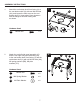
SAFETY INFORMATION Please read and understand this entire manual before attempting to assemble, operate or install the product. If you have any questions regarding the product, please call customer service at: 1-877-447-4768, 8:30 a.m. – 4:30 p.m., CST, Monday – Friday. DANGER • Do not use in an explosive atmosphere. Keep grill area clear and free from combustible materials, gasoline and other flammable vapors and liquids. CAUTION • Never use charcoal or lighter fluid with the grill.
SAFETY INFORMATION WARNING • Do not place the grill under overhead combustible construction or awnings. Minimum clearance from sides and back of unit to combustible construction, 36 inches (914.4mm) from sides and back. 36in 36in 914.4mm 914.4mm NOTE: The installation must conform with local codes or, in the absence of local codes, with either the National Fuel Gas Code, ANSI Z223.1/NFPA 54, Natural Gas and Propane Installation Code, CSA B149.1, or Propane Storage and Handling Code, B149.2.
PACKAGE CONTENTS E B F A G B1 C I J K L H M D R N D N S O T P A1 U Q Z V X W Y PART A B C D E F G H I J K L M N DESCRIPTION Hood Handle Temp Gauge Grill Body Assembly Control Knob Warming Rack Cooking Grate Heat Tent Control Knob Bezel Side Burner Left Side Table Assembly Right Side Burner Body Assembly Grease Pan Grease Cup Door Handle QTY 1 1 1 7 1 3 6 1 1 1 1 1 1 2 PART O P Q R S T U V W X Y Z A1 B1 5 DESCRIPTION Cart Left Side Panel Assembly Left Door Assembly Tank Exclusion
HARDWARE CONTENTS AA BB CC DD EE FF M6x16 Bolt M6 Spring Washer M6 Plain Washer M4x10 Bolt M6 Wingnut Qty. 16 Qty. 16 Door Upper Hinge Pin Qty. 36 Qty. 8 Qty. 2 Qty. 2 GG M10-M6 Wrench Qty. 1 PREPARATION Before beginning assembly of product, make sure all parts are present. Compare parts with package contents list on previous page and hardware contents above. If any part is missing or damaged, do not attempt to assemble the product. Contact customer service for replacement parts.
ASSEMBLY INSTRUCTIONS 1. Attach the cart bottom shelf front facing (V) to the cart bottom shelf (U) with two M6x16 bolts (AA), and loosen the tank screw on the cart bottom shelf (U), keep about 5mm clearance with the flange in the tank nesting hole as shown. 1 AA V U Hardware Used AA 2.
ASSEMBLY INSTRUCTIONS 3. Attach the two locking swivel casters (X) and the two non-locking swivel casters (Y) to the cart left side panel assembly (O) and the cart right side panel assembly (A1) with the M10-M6 wrench (GG). 3 X 4. M10-M6 Wrench X O Hardware Used GG Y A1 x1 Attach the cart rear panel (T) to the cart left side panel assembly (O) and the cart right side panel assembly (A1) with the four M6x16 bolts (AA), M6 spring washers (BB), and M6 plain washers (CC).
ASSEMBLY INSTRUCTIONS 5. Attach the upper front door brace (R) to the cart left side panel assembly (O) and the cart right side panel assembly (A1) with four M6x16 bolts (AA), M6 spring washers (BB), and M6 plain washers (CC). Hardware Used 6.
ASSEMBLY INSTRUCTIONS 7. Attach the cylinder rear block bar (S) to the cart left side panel assembly (O) and the cart right side panel assembly (A1) with two M6x16 bolts (AA). 7 S AA A1 Hardware Used AA 8. M6x16 Bolt x2 Attach the tank exclusion (Q) to the cart left side assembly (O) and the cart bottom shelf (U) with two M4x10 bolts (DD).
ASSEMBLY INSTRUCTIONS 9. Attach the door handle (N) to the left door assembly (P) and the right door assembly (Z), with four M6x16 bolts (AA). 9 N N AA Hardware Used AA M6x16 Bolt x4 Z P 10. Insert the bottom axis in the left door assembly (P) into the hole on the cart bottom shelf front facing (V), and insert the door upper hinge pin (EE) into the holes on the upper front door brace (R) and the upper hole on the left door assembly (P) as shown. Repeat with the right door assembly (Z).
ASSEMBLY INSTRUCTIONS 11. Attach the hood handle (A) to the grill body assembly (C) with two M6 wingnuts (FF), M6 spring washers (BB) and M6 plain washers (CC). 11 A CC BB FF Hardware Used 12. BB M6 Spring Washer x2 CC M6 Plain Washer x2 FF M6 Wingnut x2 Remove pre-assembled wingnut and plain washer from the temp gauge (B), then attach the temp gauge (B) to the grill body assembly (C). Secure the temp gauge (B) with wingnut and plain washer removed earlier in this step.
ASSEMBLY INSTRUCTIONS 13. Assemble the grill body assembly (C) onto the cart assembly with four M6x16 bolts (AA). 13 C AA Hardware Used AA 14. M6x16 Bolt x4 Pre-assemble two M6x16 bolts (AA) onto the grill body assembly (C) and do not tighten them. Make sure to leave a 5mm gap between the bolt and grill body’s end cap. Then hang the left side table assembly (J) on the bolts and fasten the left side table assembly (J) with three M6x16 bolts (AA) and tighten all bolts.
ASSEMBLY INSTRUCTIONS 15. Pre-Assemble two M6x16 bolts (AA) onto the grill body assembly (C) and do not tighten them. Make sure to leave a 5mm gap between the bolt and grill body’s end cap. Then hang the right side burner body assembly (K) on the bolts and fasten the right side burner body assembly (K) with three M6x16 bolts (AA) and tighten all bolts.
ASSEMBLY INSTRUCTIONS 16. Use two M4x10 bolts (DD) to assemble the side burner valve assembly and control knob bezel (H) to the right side burner body assembly (K). 16 K DD Hardware Used DD M4x10 Bolt x2 H 17. Use two M4x10 bolts (DD) to assemble side burner (I) onto the right side burner body assembly (K), (please ensure that the gas valve orifice is correctly positioned inside the side burner inlet (venturi)), and assemble the ignition wire to the side burner electrode.
ASSEMBLY INSTRUCTIONS WARNING: IT IS VERY IMPORTANT TO CHECK AND ENSURE THAT EACH AND EVERY BURNER IS FULLY ENGAGED WITH THE ADJACENT VALVE ORIFICE BEFORE COMPLETING STEP 18. FAILURE TO DO SO MAY RESULT IN FIRE OR EXPLOSION, POSSIBLY CAUSING SERIOUS INJURY OR DEATH. REFER TO MAINTENANCE SECTION INSTRUCTIONS TO PROPERLY CHECK THE ENGAGEMENT. Wrong Wrong Correct 18. Assemble the seven control knobs (D) to the valve stems. 18 D 19. Put six heat tents (G) in place over each burner.
ASSEMBLY INSTRUCTIONS 20. Put three cooking grates (F) and one warming rack (E) in place. 20 E F 21.
ASSEMBLY INSTRUCTIONS 22. Open the left door assembly (P) and the right door assembly (Z), insert the hose/regulator assembly into the cart assembly through the clearance above the cart right side panel assembly (A1). Place LP gas cylinder (sold separately) into the nesting hole located in the cart bottom shelf (U). Rotate the LP gas cylinder until the hose/regulator coupling aligns with the threaded valve of the cylinder.
REPLACEMENT PARTS LIST 23 3 48 43 1 2 22 49 4 44 24 5 50 25 51 9 6 26 27 7 45 28 14 8 10 11 13 29 30 17 31 18 15 16 20 32 30 33 35 19 29 34 36 21 42 37 38 46 47 39 12 40 41 30
REPLACEMENT PARTS LIST For replacement parts, call our customer service department at 1-877-447-4768, 8:30 a.m. – 4:30 p.m., CST, Monday – Friday.
REPLACEMENT PARTS LIST For replacement parts, call our customer service department at 1-877-447-4768, 8:30 a.m. – 4:30 p.m., CST, Monday – Friday.
BARBECUE AU GAZ LP À 6 BRÛLEURS AVEC BRÛLEUR DE CÔTÉ Modèle #DGB610SSP JOIGNEZ VOTRE REÇU ICI Numéro de série_____________________________ Date d’achat _____________________ Des questions, des problèmes, des pièces manquantes? Avant de retourner l’article au détaillant, appelez notre service à la clientèle au 1-877-447-4768, 08:30-16 heures 30, HNC, du lundi - vendredi ou par e-mail à customerservice@ghpgroupinc.com. 70-10-128 33 Rev.
TABLE DES MATIÈRES Consignes de sécurité................................................................................................................. Contenu de l’emballage............................................................................................................... Quincaillerie incluse.................................................................................................................... Préparation...........................................................................
CONSIGNES DE SÉCURITÉ Assurez-vous de lire et de comprendre l’intégralité de ce manuel avant de tenter d’assembler, d’utiliser ou d’installer le produit. Si vous avez des questions concernant ce produit, veuillez téléphoner au service à la clientèle au 1-877-447-4768, 08:30-16 heures 30, HNC, du lundi - vendredi. DANGER • N’utilisez pas le barbecue dans un endroit présentant un risque d’explosion.
CONSIGNES DE SÉCURITÉ AVERTISSEMENT • Ne pas utiliser cet appareil sous une surface combustible ou un auvent. Dégagement minimal entre les parois latérales et l’arrière de l’appareil et la construction combustible (914,4 mm (36 po) à partir des parois latérales et 914,4 mm (36 po) à partir de l’arrière). 36in 36in 914.4mm 914.4mm REMARQUE : L’installation doit être effectuée conformément à la réglementation locale ou, en l’absence d’une telle réglementation, au National Fuel Gas Code, ANSI Z223.
CONTENU DE L’EMBALLAGE E B F A G B1 C I J K L H M R N D D N S O T P A1 U Q Z V X W Y PIÈCE A B C D E F G H I J K L M N O DESCRIPTION QTÉ Manche du couvercle 1 Gauge de température 1 Corps de la grille 1 Bouton de contrôle 7 Rack de réchauffement 1 Grille de cuisson 3 Tente de chaleur 6 Collerette du bouton de contrôle 1 Brûleur de côté 1 Assemblage de la tablette de gauche 1 Assemblage du brûleur de droite 1 Réceptacle de graisse 1 Tasse pour la graisse 1 Manche de porte 2 Assemblag
QUINCAILLERIE INCLUSE (grandeur réelle) AA BB CC DD EE FF M6x16 Vis M6 Rondelle a Ressort M6 Rondelle Plate M4x10 Vis M6 Ecrou a Oreilles Qte. 16 Qte. 16 Axe Superieur de la Porte Qte. 36 Qte. 8 Qte. 2 Qte. 2 GG M10-M6 Cle Qte. 1 PRÉPARATION Avant de commencer l’assemblage du produit, assurez-vous d’avoir toutes les pièces. Comparez les pièces dans l’emballage avec la liste des pièces de la page précédente et la quincaillerie indiquée ci-dessus.
INSTRUCTIONS POUR L’ASSEMBLAGE 1. Attacher la devanture de l’étagère du bas(V) à l’étagère du bas (U) avec deux boulons M6X16 (AA). Dévisser la visse du réservoir sur l’étagère du bas (U), en gardant une espace de 5mm entre la bride du trou d’imbrication du réservoir et le bord de l’étagère tel qu’indiqué. 1 AA V U Quincaillerie utilisée AA 2.
INSTRUCTIONS POUR L’ASSEMBLAGE 3. Attacher les deux roulettes pivotantes à freins (X) et les deux roulettes pivotantes libres (V) au panneau du côté gauche (O) et le panneau du côté droit (A1) avec la clef M10-M6 (GG). 3 X 4. M10-M6 Clé X O Quincaillerie utilisée GG Y A1 x1 Attacher le panneau arrière (T) au côté gauche du chariot (O) et le côté droit (A1) avec quatre boulons M6X16 (AA), rondelles (BB) et rondelles simples M6 (CC).
INSTRUCTIONS POUR L’ASSEMBLAGE 5. Attacher la minerve de la porte de devant (R) au panneau gauche du côté (O) et le panneau de droite (A1) avec quatre boulons M6x16 (AA), rondelles M6 (BB) et rondelles simples (CC). Quincaillerie utilisée 6. AA M6x16 Vis x4 BB M6 Rondelle a Ressort x4 CC M6 Rondelle Plate x4 Attacher l’aimant (W) sur l’étagère du bas du chariot (U) ave deux boulons M4x10 (DD).
INSTRUCTIONS POUR L’ASSEMBLAGE 7. Attacher la barre cylindrique arrière (S) au panneau gauche (O) et le panneau droit (A1) du chariot avec deux boulons M6X16 (AA). 7 S AA A1 Quincaillerie utilisée AA 8. M6x16 Vis x2 Attacher l’exclusion du réservoir (bonbonne) (Q) au panneau de gauche (O) et l’étagère du bas (U) avec deux boulons M4x10 (DD).
INSTRUCTIONS POUR L’ASSEMBLAGE 9. Attacher les poignées de porte (N) aux portes gauche (P) et droite (Z) avec quatre boulons M6X16 (AA). 9 N N AA Quincaillerie utilisée AA M6x16 Vis x4 Z P 10. Insérer l’axe inférieur de la porte gauche (P) dans le trou sur la devanture de l’étagère du bas (V) et insérer la goupille de gond supérieur (EE) dans les trous sous la minerve de la porte de devant (R) et le trou supérieur de l’assemblage de la porte gauche (P) tel qu’indiqué.
INSTRUCTIONS POUR L’ASSEMBLAGE 11. Attacher la poignée du couvercle (A) au corps de la grille (C) avec deux écrous à ailettes M6 (FF), rondelles M6 (BB) et rondelles simples (CC). 11 A CC BB FF Quincaillerie utilisée 12. BB M6 Rondelle a Ressort x2 CC M6 Rondelle Plate x2 FF M6 Ecrou a Oreilles x2 Enlever l’écrou à ailettes pré-assemblage et la rondelle simple de la gauge à température (B), ensuite attacher la gauge à température (B) au couvercle (C).
INSTRUCTIONS POUR L’ASSEMBLAGE 13. Monter le corps de la grille (C) sur le chariot assemblé avec quatre boulons M6X16 (AA). 13 C AA Quincaillerie utilisée AA 14. M6x16 Vis x4 Insérer deux boulons M6X16 (AA) sur le corps de la grille (C) et ne pas serrer. Laisser une espace de 5mm entre le boulon et le bouchon terminal du corps de la grille. Ensuite accrocher l’assemblage de la tablette gauche (J) sur les têtes des boulons et serrer la tablette gauche (J) avec trois boulons M6X16 (AA).
INSTRUCTIONS POUR L’ASSEMBLAGE 15. Insérer deux boulons M6X16 (AA) sur l’assemblage de la grille (C) du côté droit, mais ne pas serrer. Laisser un minimum de 5 mm d’espace entre la tête du boulon et le bouchon terminal du corps de la grille. Ensuite accrocher le côté droit de l’assemblage du brûleur du côté droit (brûleur secondaire) (K) sur les boulons et attacher le brûleur (K) avec trois boulons M6X16 (AA) et serrer tous les boulons.
INSTRUCTIONS POUR L’ASSEMBLAGE 16. Utiliser deux boulons M4X10 (DD) pour assembler la valve du brûleur et le chaton du bouton de contrôle (H) au corps du brûleur du côté droite (K). 16 K DD Quincaillerie utilisée DD M4x10 Vis x2 H 17.
INSTRUCTIONS POUR L’ASSEMBLAGE AVERTISSEMENT: IL EST TRÈS IMPORTANT DE VÉRIFIER ET DE S’ASSURER QUE CHAQUE BRÛLEUR EST CORRECTEMENT RACCORDÉ À SA VALVE ADJACENTE AVANT DE COMPLÉTER L’ÉTAPE 18. NE PAS FAIRE CELA PEUT CAUSER UN INCENDIE OU EXPLOSION, CAUSANT DES BLESSURES GRAVES OU LA MORT. CONSULTEZ LA SECTION SUR LES INSTRUCTION D’ENTRETIEN AFIN DE VOUS ASSURER QUE L’INSTALLATION EST CORRECTE. Inadéquat Inadéquat Adéquat 18. Assembler les sept boutons de contrôle (D) sur les tiges de valves. 18 D 19.
INSTRUCTIONS POUR L’ASSEMBLAGE 20. Mettre trois grilles de cuisson (F) et un rack de réchauffement (E) en place. 20 E F 21. Mettre le réceptacle de graisse (L) et la tasse à graisse (M) en place.
INSTRUCTIONS POUR L’ASSEMBLAGE 22. Ouvrir la porte gauche (P) et la porte droite (Z). Insérer le tuyau de réglage dans l’assemblage du chariot par l’ouverture au-dessus du panneau de droite (A1). Placer la bonbonne de gaz LP (vendu séparément) dans le trou de l’étagère du bas (U). Tourner la bonbonne jusqu’à ce que le tuyau de réglage s’aligne ave le port d’entrée de la bonbonne. Serrer la jonction du tuyau de réglage au port d’entrée de la bonbonne à la main.
LISTE DES PIÈCES DE RECHANGE 23 3 48 43 1 2 22 49 4 44 24 5 50 25 51 9 6 26 27 7 45 28 14 8 10 11 13 29 30 17 31 18 15 16 20 32 30 33 35 19 29 34 36 21 42 37 38 46 47 39 12 40 41 62
LISTE DES PIÈCES DE RECHANGE Pour les pièces détachées, appelez notre service à la clientèle au 1-877-447-4768, 8 heures 30-16h30, HNC, du lundi - vendredi.
LISTE DES PIÈCES DE RECHANGE Pour les pièces détachées, appelez notre service à la clientèle au 1-877-447-4768, 8 heures 30-16h30, HNC, du lundi - vendredi.
PARRILLA A GAS PL DE 6 FOGONES CON QUEMADOR LATERAL Modelo #DGB610SSP ADJUNTE SU RECIBO AQUÍ Número de serie _______________________ Fecha de compra __________________ ¿Preguntas, problemas, piezas faltantes? Antes de volver a la tienda, llame a nuestro Departamento de Servicio al Cliente al 1-877-447-4768, de 8:30 am - 4:30 pm, hora central, de lunes - viernes o envíe un correo electrónico a customerservice@ghpgroupinc.com. 70-10-128 65 Rev.
INDICE Informacion de seguridad............................................................................................................ Contenido del paquete................................................................................................................ Aditamentos................................................................................................................................ Preparacion.......................................................................................
INFORMACION DE SEGURIDAD Lea y comprenda completamente este manual antes de intentar ensamblar, usar o instalar el producto. Si tiene preguntas relacionadas con el producto, lIame al Servicio al Cliente al: 1-877-447-4768, de 8:30 am - 4:30 pm, hora central, de lunes - viernes. PELIGRO • No utilice la unidad en un entorno explosivo. No debe haber materiales combustibles, gasolina ni otros vapores o Iiquidos inflamables cerca de la parrilla.
INFORMACIÓN DE SEGURIDAD ADVERTENCIA • No coloque la parrilla debajo de construcciones o cobertizos inflamables. Debe haber un espacio de separación mínimo de 91,44 cm (36”) desde los lados y la parte posterior de la unidad hasta construcciones de material combustible. 36in 36in 914.4mm 914.4mm NOTA: La instalación debe cumplir con loscódigos locales o, en su defecto, con el National Fuel Gas Code, ANSI Z223.1/ NFPA 54, Natural Gas and Propane Installation Code, CSA B149.
CONTENIDO DEL PAQUETE E B F A G B1 C I J K L H M R N D D N S O T P A1 U Q Z V X W Y PIEZA A B C D E F G H I J K L M N DESCRIPCIÓN CANT Manija de la Tapa 1 Indicador de Temperatura 1 Conjunto del Cuerpo de la Parrilla 1 Boton de Control 7 Rejilla de Calentamiento 1 Parrilla de Cocción 3 Carpas de Calor 6 Bisel del control de la perilla 1 Quemador Lateral 1 Conjunto de la Mesa Lateral Izquierdo 1 Conjunto del Cuerpo del Quemador 1 Lateral Derecha Cacerola de grasa 1 Tasa de Grasa 1 Ma
ADITAMENTOS (se muestran en tamano real) AA BB CC DD EE FF M6x16 Tornillo M6 Arandela Resorte M6 Arandela M4x10 Tornillo Cant. 16 Cant. 8 Puerta Superior Bisagra Pin M6 Ala de Tuerca Cant. 36 Cant. 16 Cant. 2 Cant. 2 GG M10-M6 Cle Cant. 1 PREPARACION Antes de comenzar a ensamblar el praducto, asegurese de tener todas las piezas. Compare las piezas con la lista del contenido del paquete de la pagina anterior y los aditamentos que aparecen arriba.
INSTRUCCIONES DE ENSAMBLAJE 1. Coloque la parte delantera de la estantería inferior hacia (V) al estante inferior del carrito (U) con dos tornillos M6x16 (AA). Afloje el tornillo del tanque en el estante inferior del carrito (U), mantenga sobre liquidación de 5mm con la brida en el agujero de anidación del tanque como se muestra. 1 AA V U Aditamentos utilizados AA 2.
INSTRUCCIONES DE ENSAMBLAJE 3. Coloque las dos ruedas de bloqueo de giro (X) y las dos ruedas giratorias no de bloqueo (Y) al conjunto del panel lateral izquierdo (O) y el conjunto del panel lateral derecho (A1) con la llave M10- M6 (GG). 3 X 4. M10-M6 Llave A1 x1 Coloque el panel del carrito trasero (T) al conjunto del panel lateral izquierdo (O) y el conjunto del panel lateral derecho (A1) con cuatro tornillos M6x16 (AA), arandelas de resorte M6 (BB) y M6 arandelas (CC).
INSTRUCCIONES DE ENSAMBLAJE 5. Coloque el tirante de la puerta superior delantera (R) en el conjunto del panel lateral izquierdo (O) y el conjunto del panel lateral derecho (A1) con cuatro tornillos M6x16 (AA), arandelas de resorte M6 (BB) y M6 arandelas (CC). Aditamentos utilizados 6. AA M6x16 Tornillo x4 BB M6 Arandela Resorte x4 CC M6 Arandela x4 Coloque el imán (W) al estante inferior del carrito (U) con dos tornillos M4x10 (DD).
INSTRUCCIONES DE ENSAMBLAJE 7. Coloque la barra de bloque posterior del cilindro (S) al conjunto del panel lateral izquierdo (O) y el conjunto del panel lateral derecho (A1) con dos tornillos M6x16 (AA). 7 S AA A1 Aditamentos utilizados AA 8. M6x16 Tornillo x2 Conecte la exclusión depósito del tanque (Q) al conjunto del panel lateral izquierdo (O) y el estante inferior del carrito (U) con dos tornillos M4x10 (DD).
INSTRUCCIONES DE ENSAMBLAJE 9. Coloque las manijas de las puertas (N) en el conjunto de la puerta izquierda (P) y el conjunto de la puerta derecha (Z), con cuatro tornillos M6x16 (AA). 9 N N AA Aditamentos utilizados AA M6x16 Tornillo x4 Z P 10.
INSTRUCCIONES DE ENSAMBLAJE 11. Coloque la manija de la tapa (A) al conjunto del cuerpo de la parrilla (C) con dos tuercas de mariposa M6 (FF), arandelas de resorte M6 (BB) y arandelas M6 (CC). 11 A CC BB FF Aditamentos utilizados BB CC FF 12. M6 Arandela Resorte x2 M6 Arandela x2 M6 Ala de Tuerca x2 Retire la tuerca mariposa preensamblada y la arandela del indicador de temperatura (B), a continuación, conecte el indicador de temperatura (B) al conjunto del cuerpo de la parrilla (C).
INSTRUCCIONES DE ENSAMBLAJE 13. Montar el conjunto del cuerpo de la parrilla (C) en el conjunto del carrito con cuatro tornillos M6x16 (AA). 13 C AA Aditamentos utilizados AA 14. M6x16 Tornillo x4 Inserte dos tornillos M6x16 (AA) en el conjunto del cuerpo de la parrilla (C) y no los apriete. Asegúrese de dejar un espacio de 5 mm entre la tapa del extremo del cuerpo de la parrilla y el tornillo.
INSTRUCCIONES DE ENSAMBLAJE 15. Inserte dos tornillos M6x16 (AA) en el conjunto del cuerpo de la parrilla (C) y no los apriete. Asegúrese de dejar un espacio de 5 mm entre la tapa del extremo del cuerpo de la parrilla y el tornillo. Luego colgar el conjunto del cuerpo del quemador lateral derecha (K) en los tornillos y fije el lado del conjunto cuerpo del quemador derecho (K) con tres tornillos M6x16 (AA) y apriete todos los tornillos.
INSTRUCCIONES DE ENSAMBLAJE 16. Utilice dos tornillos M4x10 (DD) para montar el conjunto de la válvula del quemador lateral y el bisel de la perilla de control (H) para el conjunto del cuerpo del quemador lateral derecha (K). 16 K DD Aditamentos utilizados DD M4x10 Tornillo x2 H 17.
INSTRUCCIONES DE ENSAMBLAJE ADVERTENCIA: ES MUY IMPORTANTE PARA COMPROBAR Y ASEGURAR QUE CADA QUEMADOR ESTÁ PLENAMENTE COMPROMETIDA CON LA VÁLVULA ADYACENTE ORIFICIO ANTES DE COMPLETAR EL PASO 18. NO HACERLO DE MAYO PROVOCAR UN INCENDIO O EXPLOSIÓN, POSIBLEMENTE CAUSAR GRAVES LESIONES O MUERTE. CONSULTE EL MANTENIMIENTO INSTRUCCIONES PARA SECCIÓN APROPIADAMENTE REVISE EL COMPROMISO. Incorrecto Incorrecto Correcto 18. Montar los siete botones de control (D) a la válvula de tallos. 18 D 19.
INSTRUCCIONES DE ENSAMBLAJE 20. Ponga tres parrillas de cocción (F) y una rejilla de calentamiento (E) en su lugar. 20 E F 21. Ponga la cacerola la grasa (L) y tasa de grasa (M) en su lugar.
INSTRUCCIONES DE ENSAMBLAJE 22. Abra el conjunto de la puerta izquierda (P) y el conjunto de la puerta derecha (Z), inserte el conjunto de la manguera/regulador en el conjunto del carrito a través del espacio libre encima del conjunto de panel lateral dere cho del carrito (A1). Coloque el cilindro de gas LP (se vende por separado) en el agujero de anidación ubicado en el estante inferior del carrito (U).
LISTA DE PIEZAS DE REPUESTO 23 3 48 43 1 2 22 49 4 44 24 5 50 25 51 9 6 26 27 7 45 28 14 8 10 11 13 29 30 17 31 18 15 16 20 32 30 33 35 19 29 34 36 21 42 37 38 46 47 39 12 40 41 94
LISTA DE PIEZAS DE REPUESTO Para obtener piezas de repuesto, llame a nuestro Departamento de Servicio al Cliente al 1-877-447-4768, de 8:30 am - 4:30 pm, hora central, de lunes - viernes.
LISTA DE PIEZAS DE REPUESTO Para obtener piezas de repuesto, llame a nuestro Departamento de Servicio al Cliente al 1-877-447-4768, de 8:30 am - 4:30 pm, hora central, de lunes - viernes.