5-BURNER LP GAS GRILL WITH SIDE BURNER . Model #DGF510SBP ANS Z21.58b- 2012 CSA 1.6b- 2012 Outdoor Cooking Gas Appliances ATTACH YOUR RECEIPT HERE Serial Number _____________________________ Purchase Date ______________________ Questions, problems, missing parts? Before returning to your retailer, call our customer service department at 1-877-447-4768, 8:30 a.m. – 4:30 p.m., CST, Monday – Friday or e-mail us at customerservice@ghpgroupinc.com. 70-10-537 1 Rev.
TABLE OF CONTENTS Safety Information ...................................................................................................................... 3 Package Contents ...................................................................................................................... 5 Hardware Contents .................................................................................................................... 6 Preparation ...................................................................
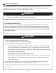
SAFETY INFORMATION Please read and understand this entire manual before attempting to assemble, operate or install the product. If you have any questions regarding the product, please call customer service at: 1-877-447-4768, 8:30 a.m. – 4:30 p.m., CST, Monday – Friday. DANGER • Do not use in an explosive atmosphere. Keep grill area clear and free from combustible materials, gasoline and other flammable vapors and liquids.
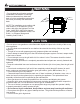
SAFETY INFORMATION WARNING • Do not place the grill under overhead combustible construction or awnings. Minimum clearance from sides and back of unit to combustible construction, 36 inches (914.4mm) from sides and back. 36in 36in 914.4mm 914.4mm NOTE: The installation must conform with local codes or, in the absence of local codes, with either the National Fuel Gas Code, ANSI Z223.1/NFPA 54, Natural Gas and Propane Installation Code, CSA B149.1, or Propane Storage and Handling Code, B149.2.
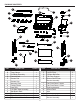
PACKAGE CONTENTS G A B H K L C I M J N O D E F S W Q R V Z T X Y U P PART DESCRIPTION A B C D E F G H I J K L M N Hood Handle Temp Gauge Grill Body Assembly Control Knob Grease Pan Grease Cup Warming Rack Cooking Grate Heat Tent Left Side Table Assembly Side Burner Rack Side Burner Right Side Burner Body Control Knob Bezel PART QUANTITY O P Q R S T U V W X Y Z 1 1 1 6 1 1 1 3 5 1 1 1 1 1 5 DESCRIPTION Left Leg Assembly Leg End Cap Cylinder Block Bar Cart Rear Support Bottom Sh
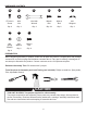
HARDWARE CONTENTS AA BB CC DD EE FF ST4.8x10 Screw M10 Nut M10-M6 Wrench M6x16 Bolt M5x12 Bolt M6 Wingnut Qty. 2 Qty. 2 Qty. 2 Qty. 34 Qty. 2 Qty. 2 GG HH II M6 Spring Washer M6 Washer M4x10 Bolt Qty. 2 Qty. 2 Qty. 2 PREPARATION Before beginning assembly of product, make sure all parts are present. Compare parts with package contents list on previous page and hardware contents above. If any part is missing or damaged, do not attempt to assemble the product.
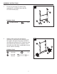
ASSEMBLY INSTRUCTIONS 1. 1 Put two leg end caps (P) under left leg assembly (O), and fasten them with two ST4.8X10 screws (AA). O Hardware Used AA ST4.8x10 Screw 2. P x2 Slide the axle (X) through the right leg assembly (V) and then put the wheels (Y) on both sides, and tighten the wheels with M10 nuts (BB) with wrenches (CC). Please note, this step requires two people to complete, and if necessary any other plier or adjustable wrench can be used for assembly.
ASSEMBLY INSTRUCTIONS 3. Use eight M6x16 bolts (DD) to assemble cart front panel - upper (T) and cart front panel lower (U) between left leg assembly (O) and right leg assembly (V). Please note the front panel - lower’s (U) direction, the side with rivet nut in the middle should be downward. 3 T V O DD Hardware Used DD 4. M6x16 Bolt x8 Use four M6X16 bolts (DD) to fasten the bottom shelf’s front bracket assembly (Z), bottom shelf’s rear bracket assembly (S) and bottom shelf (W).
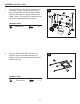
ASSEMBLY INSTRUCTIONS 5. Assemble bottom shelf assembly to the left leg assembly (O) and right leg assembly (V) with four M6X16 bolts (DD). 5 O V DD Hardware Used DD M6x16 Bolt x4 Bottom Shelf Assembly 6. Use four M6x16 bolts (DD) to fasten the cart rear support (R) to the left and right leg assembly. Please note the cart rear support’s (R) direction, the side with the rivet nut in the middle should be upward.
ASSEMBLY INSTRUCTIONS 7. Assemble the hood handle (A) to the hood with two wingnuts (FF) and two spring washers (GG) and two M6 washers (HH). 7 A HH GG FF Hardware Used 8. FF M6 Wingnut x2 GG M6 Spring Washer x2 HH M6 Washer x2 Assemble the temp gauge (B) onto the hood. Please use the washer and wing nut pre-assembled with temp gauge to install the temp gauge (B) onto the hood.
ASSEMBLY INSTRUCTIONS 9. Assemble the grill body assembly (C) onto the cart assembly with four M6x16 bolts (DD). 9 C DD Hardware Used DD 10. M6x16 Bolt x4 Pre-assemble two M6x16 bolts (DD) onto the grill body assembly (C) and do not tighten them and make sure to leave a 5mm gap between the bolt and grill body’s end cap. Then hang the left side table assembly (J) on the bolts and fasten the left side table assembly (J) with three M6x16 bolts (DD) and tighten all bolts.
ASSEMBLY INSTRUCTIONS 11. Pre-assemble two M6x16 bolts (DD) onto the grill body assembly (C) and do not tighten them and make sure to leave a 5mm gap between the bolt and grill body’s end cap. Then hang the right side burner body (M) on the bolts and fasten the right side burner body (M) with three M6x16 bolts (DD) and tighten all bolts. 11 C M DD Hardware Used DD 12.
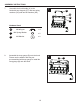
ASSEMBLY INSTRUCTIONS 13. Disassemble two M4x10 bolts that are preassembled on the side burner (L) and use them to assemble the side burner (L) on the right side burner body (M). Please ensure the gas valve orifice is correctly positioned inside side burner inlet (venturi). 13 M L Correct Incorrect Incorrect 14. 2 Bolts previously disassembled Connect the side burner sparker wire to the side burner sparker.
ASSEMBLY INSTRUCTIONS 15. Put the side burner rack (K) in place. 15 K 16. Assemble the six control knobs (D).
ASSEMBLY INSTRUCTIONS 17. Put the five heat tents (I) into place over each burner. 17 18. Put three cooking grates (H) and one warming rack (G) in place.
ASSEMBLY INSTRUCTIONS 19. Place grease pan (E) and grease cup (F) in place. 19 E F 20. Place gas cylinder (sold separately) into the nesting hole located in the Bottom shelf (W). Rotate the gas cylinder until the hose/regulator coupling aligns with the threaded valve of the cylinder. Hand-tighten the hose/regulator coupling to the threaded valve of the LP gas cylinder.
OPERATION INSTRUCTIONS CHECKING FOR LEAKS After all connections are made, check all connections and fittings on the LP gas tank valve, gas hose and regulator for leaks with a water and soap solution. To prevent fire or explosion while testing for a leak: • Always perform leak test prior to lighting the grill. • Do not smoke while testing for a leak. • Always perform leak tests outdoors in a well-ventilated area. • Do not use any source of flame while testing for leaks.
OPERATION INSTRUCTIONS CONNECTING GAS CYLINDER The propane gas supply cylinder to be used must be constructed and marked in accordance with the Specifications for LP Gas Cylinders of the U.S. Department of Transportation (D.O.T.) or the National Standard of Canada, CAN/CSA-B339, Cylinders, Spheres and Tubes for Transportation of Dangerous Goods; and Commission, as applicable; and provided with a listed overfilling prevention device. Use only 20-pound cylinders (height: 18.11 inches, tank diameter: 9.
OPERATION INSTRUCTIONS NOTE: Other cylinders may be acceptable for use with this appliance provided they are compatible with the appliance nesting hole and retention means. Refer to Step 20 of the Assembly Instructions for correct cylinder to cylinder holder connection. WARNING ALL INSTRUCTIONS AND SAFEGUARDS ON THIS PAGE MUST BE FOLLOWED TO PREVENT FIRE, DAMAGE AND/OR INJURY. CONNECTING THE LP TANK 1. The knob on the LP tank must be closed. Make sure that the knob is turned clockwise to a full stop.
OPERATION INSTRUCTIONS Lighting The Grill Before first use: Remove all hangings or plastic straps, if present. Before you cook on your new gas grill, it is important to clean your grill with heat. To do this, operate the grill for approximately 15 minutes with the lid closed and the control knob in the highest position. This will clean the internal parts by burning off any residue and odor from the manufacturing process.
OPERATION INSTRUCTIONS LIGHTING THE GRILL WITH A MATCH 1. Open the lid. 2. Insert a match in the end of the match holder that is installed on the right leg assembly. 3. Light the match. 4. Immediately place the lit match through the spaces in the grill gates near the ports of the burner between the heat tents as shown. Make sure the lit match is close to the burner ports. 5.
CARE AND MAINTENANCE Cooking Grates The best time to ‘burn-off’ the cooking grates is after every use (approx. 15 minutes). The grill is already hot from cooking thus requiring less fuel to obtain necessary temperature for ‘burn-off’. To ‘burn off’ or heat clean your grill, turn the burners to highest position and run for 15 minutes with the lid closed. Then turn off the burners and use a wire brush to clean excess food residue from the grates.
CARE AND MAINTENANCE Burner Assembly Warming Rack Removing The Burner Assembly Cooking Grates 1. Make sure all control knobs are in the OFF position, gas supply valve is closed, and the gas hose is disconnected from the gas supply. Heat Tents 2. Open lid and remove warming rack, cooking grates, heat tents, clip for burner, ignition chain and main burner. 3. Remove hinge pin as illustrated in Figure 1. 4. Slide main burmers out of firebox. 5. Detach ignition wire from electrode in Figure 2.
CARE AND MAINTENANCE Cleaning the Burner Assembly – Make sure the grill is cool 1.Turn gas off at the control knobs and LP gas cylinder. 2.Disconnect LP gas cylinder from regulator and hose. 3.Remove warming rack, cooking grates and heat tents. 4.Detach burner by removing the cotter pins at the back of the burners to detach them from the brackets. 5.Detach ignition wire from electrode by hand only. DO NOT use pliers or any other tool as it may damage the electrode or wire. 6.Lift burner slowly. 7.
TROUBLESHOOTING If you have any questions regarding the product, please call customer service at 1-877-447-4768, 8:30 a.m. – 4:30 p.m., CST, Monday – Friday. PROBLEM POSSIBLE CAUSE CORRECTIVE ACTION The burner will not light using the ignitor procedure (weak or no spark being generated). 1. The igniter electrode may be covered with grease or residue. 2. The igniter electrode may have a loose or disconnected wire. 3. Cracked or broken ignition electrode. 1. Clean the ignitor electrode. Low Heat. 1.
TROUBLESHOOTING PROBLEM POSSIBLE CAUSE CORRECTIVE ACTION The burner will not light with a match. 1. Match not reaching burners (when holding match with hand). 2. Empty tank. 1. Use match holder found in cabinet door. 3. Poor connection between valve regulator and LP cylinder coupling. 4. Burner inlet blocked. No gas flow or an 1. Tank valve not on or fully obstructed gas flow. opened. 2. Empty tank. 3. Poor connection between valve regulator and LP cylinder coupling. 4. Burner inlet blocked.
LIMITED WARRANTY 1-Year Limited Warranty This LP gas grill is warranted for 1 year (5 years on the Stainless Steel burners) against broken or damaged parts at the time of purchase. It is warranted to be free of defects. Paint is warranted to be free of defects except for rust, which may appear after repeated use. This warranty does not cover damage or issues related to neglect, abuse, or modifications to the appliance. Repair labor is not covered.
REPLACEMENT PARTS LIST 2 3 1 12 13 4 31 14 5 15 32 6 33 16 34 7 8 18 17 19 20 21 9 36 35 23 22 37 23 24 10 24 38 25 39 26 27 40 29 43 11 44 41 30 28 42 28
REPLACEMENT PARTS LIST For replacement parts, call our customer service department at 1-877-447-4768, 8:30 a.m. – 4:30 p.m., CST, Monday – Friday.
REPLACEMENT PARTS LIST For replacement parts, call our customer service department at 1-877-447-4768, 8:30 a.m. – 4:30 p.m., CST, Monday – Friday.