3 BURNER PREMIER NATURAL GAS GRILL Model #DGP397SNN / DGP397SNN-D / DGP397CNN / DGP397CNN-D / DGP397GNN / DGP397GNN-D / DGP397MNN / DGP397MNN-D Français XX Français p. p. 30 XX Español Españolp.p.59 ATTACH YOUR RECEIPT HERE Serial Number _____________________________ Purchase Date ______________________ Questions, problems, missing parts? Before returning to your retailer, call our customer service department at 1-877-447-4768, 8:00 a.m. – 4:30 p.m.
TABLE OF CONTENTS Safety Information ...................................................................................................................... 3 Package Contents ...................................................................................................................... 5 Hardware Contents .................................................................................................................... 6 Preparation ...................................................................
SAFETY INFORMATION Please read and understand this entire manual before attempting to assemble, operate or install the product. If you have any questions regarding the product, please call customer service at: 1-877-447-4768, 8:00 a.m. – 4:30 p.m., CST, Monday – Friday. DANGER • Do not use in an explosive atmosphere. Keep grill area clear and free from combustible materials, gasoline and other flammable vapors and liquids.
SAFETY INFORMATION WARNING • Do not place the grill under overhead combustible construction or awnings. Minimum clearance from sides and back of unit to combustible construction, 36 inches (914.4mm) from sides and back. 36in 36in 914.4mm 914.4mm NOTE: The installation must conform with local codes or, in the absence of local codes, with either the National Fuel Gas Code, ANSI Z223.1/NFPA 54, Natural Gas and Propane Installation Code, CSA B149.1, or Propane Storage and Handling Code, B149.2.
PACKAGE CONTENTS A B C D R E Q P F S O T Z U V N G W X M H L PART DESCRIPTION K QUANTITY PART J I Y DESCRIPTION QUANTITY A Hood Handle 1 N Door Handle 1 B Temp Gauge 1 O Left Side Shelf Assembly 1 C Grill Body Assembly 1 P Heat Tent 3 D Side Shelf Bracket A 2 Q Cooking Grate 2 E Right Side Shelf Assembly 1 R Warming Rack 1 F Side Shelf Bracket B 2 S Control Knob 3 G Cart Right Side Panel Assembly 1 T Grease Pan 1 H Locking Swivel Caster 2
HARDWARE CONTENTS AA BB CC DD EE FF M6x16 Bolt M6 Spring Washer Qty. 2 M6 Wing Nut M6x35 Bolt M3x10 Bolt Qty. 18 M6 Plain Washer Qty. 2 Qty. 2 Qty. 4 Qty. 4 GG HH II JJ M6x12 Flat Bolt Shoulder Bolt Wrench M4x12 Bolt Qty. 8 Qty. 4 Qty. 1 Qty. 2 PREPARATION Before beginning assembly of product, make sure all parts are present. Compare parts with package contents list on previous page and hardware contents above.
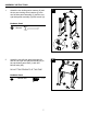
ASSEMBLY INSTRUCTIONS II 2 Qty. 1 AA AA J M6 Washer Qty. 2 HH Shoulder Bolt Qty.4 Qty. 18 GG M6x12 Flat Bolt Qty. 8 J M6x16 Bolt x4 Wrench II BB DO NOT TIGHTEN BOLTS AT THIS TIME. Hardware Used M6x16 Bolt LL AA Used Attach the cart left side panel Hardware assembly (L) AA M6x16 Bolt and the cart right side panel assembly (G) to the cart bottom panel shelf (J) with four M6x16 bolts (AA). AA G G II Qty. 4 Qty. 2 Qty. 4 M6x35 Bolt M6 Wing Nut M6 Spring Washer Qty.
Qty. Wre II Qty. 2 Qty.4 Shoulder Bolt HH Qty. 1 Qty. 8 M6x12 Flat Bolt Wrench GG M6 Wing Nut Qty.4 HH GG 8 G Qty. 8 Qty. 2 Qty. 18 x4 L Shoulder Bolt M6 Washer 4 M6x16 Bolt M6x16 Bolt G G M6x12 Flat Bolt CC Hardware Used KK AA AA BB Attach the cart rear panel (W) to the cart left side panel assembly (L) and the cart right side panel assembly (G) with the four M6x16 bolts (AA). AA KK AA 4. x2 G G M6 Spring Washer Qty.
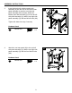
ASSEMBLY INSTRUCTIONS 5. BB Attach the upper front door brace (V) to the cart left side panel assembly (L) and the cart Hardware Used right side panel assembly (G) with four M6x35 EE M6x35 Bolt bolts (EE). CC DD EE M6 Washer M6 Spring Washer Qty. 2 Qty. 2 M6x35 Bolt EE Qty. 2 HH VV EE EE x4 LL x4 Hardware Used M6 Wing Nut G FF EE Hardware Used 5 M6x35 Bolt G V EE x4 M6x35 Bolt M3x10 Bolt Qty. 4 Qty. 4 L II Shoulder Bolt Wrench Qty.
M6 Spring Washer Qty. 2 Attach the door handle (N) to the door assembly (M) with two M6x16 bolts (AA). HH Shoulder Bolt Qty.4 GG M6x12 Flat Bolt Qty. 8 M6x16 Bolt Qty. 2 AA AA Hardware Used M6x16 Bolt Qty. 18 AA M6 Washer BB Hardware Used 7 M6x16 Bolt 7. CC ASSEMBLY INSTRUCTIONS x2 x2 M NN AA 8.
ASSEMBLY INSTRUCTIONS 9. Hardware Used AA BB CC DD M6x16 Bolt Qty. 18 GG 9 Attach the hood handle (A) to the grill body assembly (C) with two M6 wing nuts (DD), two M6 spring washers (CC) and two M6 plain washers (BB). Hardware Used BB M6 Plain Washer x2 CC M6 Spring Washer Hardware Used x2 M6 Wing Nut BB M6 Plain Washer x2 AADD M6 Plain AA Washer BB BB CC M6 Spring Washer M6x16 BB GG HH M6x12 Flat Bolt CC x2 x 2 M6 M6 Wing Nut M6 Spring Qty. M62 Washer Wing Qty.
Qty. 1 Wrench II C Qty.4 Shoulder Bolt HH Qty. 1 Qty. 8 G M6x12 Flat Bolt Wrench Qty. 2 M6 Wing Nut Pre-assemble two M6x16 bolts (AA) onto the cart right side panel assembly (G) and do not tighten them. Make sure to leave a 5mm gap between the bolt and the panel. Hang the natural gas hose bracket onto the bolts and tighten the two bolts. Put the two-piece natural gas hose holders (Y) on the hose. Attach the natural gas hose holders (Y) to the bottom shelf (J) with two M4x12 bolts (JJ).
M6 Spring Washer Qty. 2 Shoulder Bolt M6x12 Flat Bolt Qty. 18 GG M6x16 Bolt AA Hardware Used M6x12 Flat Bolt x8 C Qty.4 HH GG Qty. 2 Attach the side shelf bracket A (D) and side shelf bracket B (F) to the grill body assembly (C) with eight M6x12 flat bolts (GG). M6 Washer BB 13. 13 C C D Qty.
Qty. 4 M6x35 Bolt EE Qty. 2 OO x4 Shoulder Bolt EE Qty. 8 x4 HH HH Qty.4 Shoulder Bolt HH Qty. 2 Qty. 18 GG M6 Washer Shoulder Bolt M6x16 Bolt HH M6x12 Flat Bolt CC Hardware Used BB 14 M6 Spring Washer Qty. 2 HH AA Qty. 1 II Attach the left side shelf assembly (O) to the brackets installed at step 13 with two shoulder bolts (HH). Repeat it for right side shelf assembly (E). Hardware Used M6 Wing Nut DD 14.
ASSEMBLY INSTRUCTIONS 15. Put three heat tents (P) in place over each burner. 15 P 16. Put two cooking grates (Q) and one warming rack (R) in place.
ASSEMBLY INSTRUCTIONS 17. Put the grease pan (T) and grease cup (U) into place. 17 TT U U 18. Assemble the three control knobs (S) to the valve stems.
ASSEMBLY INSTRUCTIONS FullyAssembled Assembled Fully Front View Front View Rear View Rear View CONNECTING THE GRILL TO THE NATURAL GAS SUPPLY • The quick disconnect socket (Z) and supply gas line must be installed by a qualified service agency. The supply connection must be made in accordance with local codes or, in the absence of local codes, with either the National Fuel Gas Code, ANSI Z223.1/NFPA 54, in the USA, of the Natural Gas and Propane Installation Code, CSA B149.1, in Canada.
ASSEMBLY INSTRUCTIONS WARNING In the connection process, make sure: • The gas supply hose does not come in contact or remain in contact with the firebox. CHECKING FOR LEAKS After all connections are made, check all connections and fittings on the natural gas quick connector, gas hose and manifold for leaks with a water and soap solution. To prevent fire or explosion while testing for a leak: • Always perform leak test prior to lighting the grill. • Do not smoke while testing for a leak.
OPERATION INSTRUCTIONS Lighting The Grill Before first use: Remove all hangings or plastic straps, if present. Before you cook on your new gas grill, it is important to clean your grill with heat. To do this, operate the grill for approximately 15 minutes with the lid closed and the control knob in the highest position. This will clean the internal parts by burning off any residue and odor from the manufacturing process.
OPERATION INSTRUCTIONS LIGHTING THE GRILL WITH A MATCH 1. Open the lid. 2. Insert a match in the end of the match holder that is installed on the inside of the cabinet door. 3. Light the match. 4. Immediately place the lit match through the spaces in the grill gates near the ports of the burner between the heat tents as shown. Make sure the lit match is close to the burner ports. 5.
CARE AND MAINTENANCE Cooking Grates The best time to ‘burn-off’ the cooking grates is after every use (approx. 15 minutes). The grill is already hot from cooking thus requiring less fuel to obtain necessary temperature for ‘burn-off’. To ‘burn off’ or heat clean your grill, turn the burners to highest position and run for 15 minutes with the lid closed. Then turn off the burners and use a wire brush to clean excess food residue from the grates.
CARE AND MAINTENANCE Burner Assembly Warming Rack Cooking Grates Removing The Burner Assembly 1. Make sure all control knobs are in the OFF position, gas supply valve is closed, and the gas hose is disconnected from the gas supply. Heat Tents 2. Open lid and remove warming rack, cooking grates, and heat tents. 3. Remove hinge pin as illustrated in Figure 1. 4. Slide main burners out of firebox. 5. Detach ignition wire from electrode in Figure 2.
CARE AND MAINTENANCE Cleaning the Burner Assembly – Make sure the grill is cool 1. Ensure all burner ports are clear of clogs. Use of a pin or paper clip works well. 2. Ensure burner is free of any damage. If damage is found, replace with new burner. 3. Ensure the end of the burner and primary air screen are clear from insect nests, dirt or debris. Re-installing the Burner Ensure that gas valve orifices are correctly positioned inside burner inlet (venturi).
TROUBLESHOOTING If you have any questions regarding the product, please call customer service at 1-877-447-4768, 8:00 a.m. – 4:30 p.m., CST, Monday – Friday. PROBLEM POSSIBLE CAUSE CORRECTIVE ACTION The burner will not light using the ignitor procedure (weak or no spark being generated). 1. The igniter electrode may be covered with grease or residue. 1. Clean the ignitor electrode. 2. The igniter electrode may have a loose or disconnected wire. 2.
TROUBLESHOOTING PROBLEM The burner will not light with a match POSSIBLE CAUSE CORRECTIVE ACTION 1. M atch not reaching burners (when holding match with hand). 1. U se match holder found in cabinet door. 3. P oor connection between gas hose plug fitting and sleeve coupling. 3. Turn off the grill knobs, close the gas supply shut-off valve and check the connection between the plug and sleeve coupling. Disconnect and reconnect, if necessary. 2. G as supply shut off. 4. B urner inlet blocked.
LIMITED WARRANTY 1-Year Limited Warranty This natural gas grill is warranted for 1 year (5 years on the Stainless Steel burners) against broken or damaged parts at the time of purchase. It is warranted to be free of defects. Paint is warranted to be free of defects except for rust, which may appear after repeated use. This warranty does not cover damage or issues related to neglect, abuse, or modifications to the appliance. Repair labor is not covered.
REPLACEMENT PARTS LIST For replacement parts, call our customer service department at 1-877-447-4768, 8:00 a.m. – 4:30 p.m., CST, Monday – Friday.
REPLACEMENT PARTS LIST For replacement parts, call our customer service department at 1-877-447-4768, 8:00 a.m. – 4:30 p.m., CST, Monday – Friday.
REPLACEMENT PARTS LIST For replacement parts, call our customer service department at 1-877-447-4768, 8:00 a.m. – 4:30 p.m., CST, Monday – Friday.
BARBECUE AU NATUREL DE PREMIÈRE QUALITÉ À TROIS BRÛLEURS Nᵒ de modèle DGP397SNN/DGP397SNN-D/ DGP397CNN/DGP397CNN-D/DGP397GNN/ DGP397GNN-D/DGP397MNN/DGP397MNN-D English p.p. 1 XX Français XX Español Españolp.p.
TABLE DES MATIÈRES Informations relatives à la sécurité ............................................................................................. 32 Contenu de l’emballage .............................................................................................................. 34 Quincaillerie fournie .................................................................................................................... 35 Préparation ....................................................................
INFORMATIONS RELATIVES À LA SÉCURITÉ Veuillez lire et comprendre le présent guide avant de tenter d’assembler, d’utiliser ou d’installer le produit. Si vous avez des questions concernant le produit, veuillez appeler le service à la clientèle au : 1 877 447‑4768, entre 8 h et 16 h 30 (HNC), du lundi au vendredi. DANGER • N’utilisez pas cet appareil dans une atmosphère explosive.
INFORMATIONS RELATIVES À LA SÉCURITÉ AVERTISSEMENT • Ne placez pas le barbecue sous des constructions inflammables ou des auvents. Le dégagement minimum entre l’appareil, sur les côtés et à l’arrière, et les constructions inflammables est de 36 po (914,4 mm). 36 po R EMARQUE : L’installation doit être conforme aux codes locaux ou, en l’absence de codes locaux, au code ANSI Z223.1/NFPA 54 intitulé « National Fuel Gas Code » (code national des gaz combustibles), au code CSA B149.
CONTENU DE L’EMBALLAGE A B C D R E Q P F S O T Z U V N G W X M H L PIÈCE DESCRIPTION K QUANTITÉ PIÈCE J I Y DESCRIPTION QUANTITÉ A Poignée du couvercle 1 N Poignée de porte 1 B Jauge de température 1 O Tablette latérale gauche 1 C Bâti du barbecue 1 P Plaque de rayonnement 3 D Support de tablette latérale A 2 Q Grille de cuisson 2 E Tablette latérale droite 1 R Grille d’attente 1 F Support de tablette latérale B 2 S Bouton de commande 3 G Panneau
QUINCAILLERIE FOURNIE AA BB CC DD EE FF Boulon M6 x 16 mm Rondelle plate M6 Rondelle élastique M6 Écrou à oreilles M6 Boulon M6 x 35 mm Boulon M3 x 10 mm Qté18 Qté 2 Qté 2 Qté 2 Qté 4 Qté. 4 GG HH II JJ Boulon plat M6 x 12 mm Boulon à épaulement Clé Boulon M4 x 12 mm Qté 8 Qté 4 Qty. 1 Qté 2 PRÉPARATION Avant de commencer l’assemblage du produit, assurez-vous d’avoir toutes les pièces.
INSTRUCTIONS D’ASSEMBLAGE 1 1. Fixez les deux roulettes à blocage (H) et les deux roulettes sans blocage (I) au panneau gauche (L) et au panneau droit (G) du chariot à l’aide de la clé (II). HH II Qty. 4 Qty. 1 Wrench AA AA J HH Shoulder Bolt Qty.4 GG M6x12 Flat Bolt Qty. 8 J Qty. 2 M6 Spring Washer Qty. 2 2 Qty. 18 AA AA Boulon M6 x 16 mm x4 M6 Washer BB NE SERREZ PAS COMPLÈTEMENT LES BOULONS À CE STADE. Matériel utilisé II M6x16 Bolt CC Hardware Used 2.
Qty. 1 Qty.4 Shoulder Bolt HH Qty. 1 Qty. 8 M6x12 Flat Bolt Wrench G G 37 Qty.4 G Qty. 8 HH GG x4 L Shoulder Bolt Qty. 2 Qty. 18 4 M6 Washer AA AA Boulon M6 x 16 mm KK AA AA M6x16 Bolt BB 4. Fixez le panneau arrière du chariot (W) au panneau gauche (L) et au panneau droit (G) du chariot avec quatre boulons M6 x 16 mm (AA). Matériel utilisé KK II GG 4 2 Qty. 2 Qty. 18 Qty. Qty. M3x10 M6 BoltSpring Washer Qty. 4Qty.
INSTRUCTIONS D’ASSEMBLAGE Fixez le support supérieur de porte (V) au panneau gauche (L) et auHardware panneau droit (G) du Used chariot avec quatre boulons M6 x 35 mm (EE). EE CC Matériel utilisé EE G M6x35 Bolt V EE x4 M6x35 Bolt M3x10 Bolt Qty. 4 Qty. 4 L II Shoulder Bolt Wrench Qty. 1 Hardware Used L x4 Fixez l’aimant de porte (X) au panneau gauche du chariot (L) avec quatre boulons M3 x 10 mm (FF). 6 Hardware Used L Boulon M3 x 10 mm M3x10 Bolt Qty. 4 M6x35 Bolt Qty.
M6 Spring Washer Qty. 2 CC INSTRUCTIONS D’ASSEMBLAGE Fixez la poignée de porte (N) à la porte (M) à l’aide de deux boulons M6 x 16 mm (AA). HH Shoulder Bolt Qty.4 GG M6x12 Flat Bolt Qty. 8 AA AA Boulon M6 x 16 mm Qty. 2 Matériel utilisé M6x16 Bolt Qty. 18 AA M6 Washer BB Hardware Used 7 M6x16 Bolt 7. x2 x2 M NN AA 8.
INSTRUCTIONS D’ASSEMBLAGE 9. Matériel utilisé AA BB CC DD M6x16 Bolt Qty. 18 GG 9 Fixez la poignée du couvercle (A) au bâti du barbecue (C) avec deux écrous à oreilles M6 (DD), deux rondelles élastiques M6 (CC) et deux rondelles plates M6 Hardware(BB). Used BB M6 Plain Washer x2 CC M6 Spring Washer Hardware Used x2 M6 Wing Nut BB M6 Plain Washer x2 AADD Rondelle M6 AA plate BB BB CC BB CC Rondelle élastique M6x16M6 DD Bolt Écrou à oreillesM6M6 M6x16 Bolt Washer Qty.
Qty. 1 Wrench II Qty.4 Shoulder Bolt HH Qty. 1 Qty. 8 GG M6x12 WrenchFlat Bolt Qty. 2 CC AA AA II x4 Placez deux boulons M6 x 16 mm (AA) sur le panneau droit (G) du chariot sans les serrer. Assurez-vous de laisser un espace de 5 mm entre les boulons et le panneau. Placez ensuite le support du tuyau du gaz naturel sur les boulons, puis serrez les deux boulons. Placez les deux attaches (Y) sur le tuyau de gaz naturel.
M6 Spring Washer Qty. 2 GG GG Boulon plat M6 x 12 mm Qty.4 Shoulder Bolt x8 C 13 C C D Qty. 8 Qty. 18 M6x16 Bolt AA Matériel utilisé M6x12 Flat Bolt HH Fixez le support de tablette latérale A (D) et le support de tablette latérale B (F) au bâti du barbecue (C) avec huit boulons plats M6 x 12 mm (GG). Qty. 2 BB 13.
Qty. 4 M6x35 Bolt EE Qty. 2 Qty.4 HH HH EE Qty. 8 Shoulder Bolt HH GG Qty. 2 Qty. 18 x4 M6x12 Flat Bolt M6 Washer HH Boulon à épaulement M6x16 Bolt BB OO x4 Shoulder Bolt Matériel utilisé AA 14 M6 Spring Washer Qty. 2 CC HH Qty. 1 II Fixez la tablette latérale gauche (O) aux supports installés à l’étape 13 avec deux boulons à épaulement (HH). Répétez cette étape pour Hardware la tablette latérale droite (E). Used M6 Wing Nut DD 14.
INSTRUCTIONS D’ASSEMBLAGE 15. Placez les trois plaques de rayonnement (P) sur chaque brûleur. 15 P 16. Placez les deux grilles de cuisson (Q) et la grille d’attente (R).
INSTRUCTIONS D’ASSEMBLAGE 17. Placez le plateau à graisse (T) ainsi que le récupérateur de graisse (U). 17 TT U U 18. Assemblez les trois boutons de commande (S) aux tiges de la vanne.
INSTRUCTIONS D’ASSEMBLAGE Fully Assembled Entièrement assemblé Vue de face Vue arrière Front View Rear View RACCORD DU BARBECUE À L’ALIMENTATION EN GAZ NATUREL • La douille de débranchement rapide (Z) et le tuyau d’alimentation en gaz doivent être installés par un service d’entretien autorisé. Le raccord d’alimentation doit être réalisé selon la réglementation locale ou, en l’absence d’une telle réglementation, selon le National Fuel Gas Code, ANSI Z223.
INSTRUCTIONS D’ASSEMBLAGE AVERTISSEMENT Lorsque vous effectuez les raccordements, assurez-vous que : • le tuyau d’alimentation en gaz ne touche pas au foyer du barbecue DÉTECTION DES FUITES Après avoir effectué tous les branchements, vérifiez s’il y a des fuites en vaporisant de l’eau savonneuse sur le raccord de gaz naturel à branchement rapide, le tuyau de gaz et le collecteur.
INSTRUCTIONS DE FONCTIONNEMENT Allumer le barbecue Avant la première utilisation : Retirez tous les emballages et toutes les attaches de plastique, le cas échéant. Avant de cuisiner sur votre nouveau barbecue au propane, il est important de le nettoyer avec de la chaleur. Pour ce faire, faites fonctionner le barbecue pendant environ 15 minutes avec le couvercle baissé et le bouton de commande à l’intensité maximale.
INSTRUCTIONS DE FONCTIONNEMENT ALLUMER LE BARBECUE AVEC UNE ALLUMETTE 1. Ouvrez le couvercle. 2. Insérez une allumette dans le porte-allumettes qui se trouve à l’intérieur de la porte du barbecue. 3. Allumez l’allumette. 4. Placez immédiatement l’allumette dans un des espaces des grilles du barbecue qui se trouvent près des orifices du brûleur, entre les plaques de rayonnement, comme illustré. Veillez à placer l’allumette près des orifices du brûleur. 5.
ENTRETIEN ET MAINTENANCE Grilles de cuisson Le moment idéal pour brûler les résidus sur les grilles de cuisson est juste après leur utilisation, pendant environ 15 minutes. Puisque le barbecue est déjà chaud, atteindre la température voulue pour le nettoyage demande moins de combustible. Pour brûler les résidus, réglez le barbecue à sa plus haute intensité et laissez-le fonctionner pendant 15 minutes à couvercle fermé.
ENTRETIEN ET MAINTENANCE Brûleur Grille d’attente Retirer le brûleur Grilles de cuisson 1. Assurez-vous que tous les boutons de commande sont en position d’arrêt, que la vanne d’alimentation en propane est fermée et que le tuyau de propane est déconnecté de l’alimentation. Plaques de rayonnement 2. Retirez la grille d’attente, les grilles de cuisson et les plaques de rayonnement. 3. Retirez l’axe de charnière, comme illustré à la figure 1. 4.
ENTRETIEN ET MAINTENANCE Nettoyer le brûleur – Assurez-vous que le barbecue est froid. 1. Veillez à ce que tous les orifices du brûleur soient libres d’obstructions. Vous pouvez utiliser une broche ou un trombone. 2. Assurez-vous que le brûleur n’est pas endommagé. S’il l’est, remplacez-le. 3. Assurez-vous que l’extrémité du brûleur et le filtre à air principal ne contiennent pas de nids d’insectes, de saletés ou de débris.
DÉPANNAGE Si vous avez des questions concernant le produit, veuillez appeler le service à la clientèle au 1 877 447‑4768, entre 8 h et 16 h 30 (HNC), du lundi au vendredi. PROBLÈME CAUSE POSSIBLE SOLUTION Le brûleur ne s’allume pas après que la procédure d’allumage a été suivie (la flamme est faible ou aucune flamme n’est produite). 1. L ’électrode de l’allumeur est peut-être recouverte de graisse ou de résidus. 1. N ettoyez l’électrode d’allumage. 2.
DÉPANNAGE PROBLÈME CAUSE POSSIBLE SOLUTION Le brûleur ne s’allume pas à l’aide d’une allumette. 1. L’allumette n’atteint pas les brûleurs (lorsque vous la tenez d’une main). 1. Utilisez le support à allumettes situé dans la porte de l’armoire. 3. Il y a un mauvais branchement entre le raccord à manchon et l’embout du tuyau de gaz. 3. Tournez les boutons de commande à la position OFF (fermé), fermez la vanne d’arrêt du gaz, puis vérifiez le branchement du raccord à manchon et de l’embout.
GARANTIE LIMITÉE Garantie limitée d’un an Ce barbecue au gaz naturel est garanti pendant un an (les brûleurs en acier inoxydable sont garantis pendant cinq ans) contre les pièces brisées ou endommagées au moment de l’achat. Il est garanti contre les défauts. La peinture est garantie contre les défauts, mais n’est pas garantie contre la rouille, qui pourrait apparaître après une utilisation répétée.
LISTE DES PIÈCES DE RECHANGE Pour des pièces de rechange, veuillez appeler le service à la clientèle au 1 877 447‑4768, de 8 h à 16 h 30 (HNC), du lundi au vendredi.
LISTE DES PIÈCES DE RECHANGE Pour des pièces de rechange, veuillez appeler le service à la clientèle au 1 877 447‑4768, de 8 h à 16 h 30 (HNC), du lundi au vendredi.
LISTE DES PIÈCES DE RECHANGE Pour des pièces de rechange, veuillez appeler le service à la clientèle au 1 877 447‑4768, de 8 h à 16 h 30 (HNC), du lundi au vendredi.
PARRILLA PREMIER CON 3 QUEMADORES PARA GAS N.° de modelo DGP397SNN / DGP397SNN-D / DGP397CNN / DGP397CNN-D / DGP397GNN / DGP397GNN-D / DGP397MNN / DGP397MNN-D English p.p. 1 XX Français Français XX Français p. p. 30 ADJUNTE SU RECIBO AQUÍ Número de serie _________________________ Fecha de compra ______________________ ¿Preguntas, problemas, piezas faltantes? Antes de hacer una devolución a la tienda, llame a nuestro Departamento de Atención al Cliente al 1-877-447-4768, de lunes a viernes de 8:00 a. m.
CONTENIDO Información de seguridad ............................................................................................................ 61 Contenido del paquete ................................................................................................................ 63 Paquete de tornillería................................................................................................................... 64 Preparación ..........................................................................
INFORMACIÓN DE SEGURIDAD Lea y comprenda este manual por completo antes de intentar ensamblar, poner en funcionamiento o instalar el producto. Si tiene preguntas relacionadas con el producto, llame al Departamento de Atención al Cliente al 1-877-447-4768, de lunes a viernes de 8:00 a. m. a 4:30 p. m. (hora central estándar). PELIGRO • N o se puede utilizar en una atmósfera explosiva.
INFORMACIÓN DE SEGURIDAD ADVERTENCIA • No coloque la parrilla debajo de toldos o estructuras combustibles. La distancia mínima desde los laterales y la parte trasera de la 36" unidad hasta una estructura combustible debe ser de 36" (914,4 mm). 914,4 mm 36" 914,4 mm N OTA: la instalación debe cumplir con los códigos locales o, en ausencia de códigos locales, con el Código Nacional de Gas Combustible ANSI Z223.1/NFPA 54, el Código de Instalación de Gas Natural y Propano CSA B149.
CONTENIDO DEL PAQUETE A B C D R E Q P F S O T Z U V N G W X M H L PIEZA DESCRIPCIÓN K J Y DESCRIPCIÓN I CANTIDAD PIEZA A Manija de la tapa 1 M Conjunto de la puerta CANTIDAD 1 B Indicador de temperatura 1 N Manija de la puerta 1 C Conjunto del cuerpo de la parrilla 1 O Conjunto de la repisa lateral izquierda 1 D Abrazadera A de la repisa lateral 2 P Protector térmico 3 E Conjunto de la repisa lateral derecha 1 Q Rejilla para cocinar 2 F Abrazadera B de la
PAQUETE DE TORNILLERÍA AA AA DD DD FF FF BB BBBB BB CC CC CC EE EE AA DD EE DD FF FF FF CC EE DD CC AAAA AAAA AA EE DD FF BBBBAABB BBCC EE DD FF CC EE DD FF CC EE DD FF BB CC EE M3x10 M3x10 M6x16 M6x16 M6x16M6 M6x35 M6x35 M6x35M3x10 M6 M6 M6 M6 M6 M6 M6 M6 M6 M6x16 M6x35 M3x10 M6 M6 M6x16 M6x35 M6 M6 M6 M3x10 M6x16 M6x35 M6 M6 M6 M3x10M3x10 M6x16 M6x35 M6 M6 Spring M6 deWing Pernos Arandela Arandela Tuerca Bolt Pernos Pernos M3x10 M6x16 M6x35 M6 M6 M6 Bolt Wing Nut Nut Bolt Bolt Bolt Bolt Washer Washer Spr
INSTRUCCIONES DE ENSAMBLAJE 1 II 2 Qty. 1 AA AA J M6 Washer Qty. 2 HH Shoulder Bolt Qty.4 Qty. 18 GG M6x12 Flat Bolt Qty. 8 J M6x16 Bolt x4 Wrench Qty. 4 Qty. 2 M6 Spring Washer Qty. 2 LL II II M6x35 Bolt M6 Wing Nut G G BB NO AJUSTE LOS PERNOS TODAVÍA. Tornillería utilizada Pernos M6 × 16 II AA CC Hardware Used 2.
Qty. 1 Shoulder Bolt Qty.4 HH Qty. 1 Qty. 8 M6x12 FlatWrench Bolt Qty.4 Qty. 8 G Shoulder Bolt HH GG L M6x12 Flat Bolt GGII Qty. 2 Qty. 18 66 Wrench Q Qty. 2 M6 Washer M6x16 Bolt 4 BB ×4 AA AA G G AA Tornillería utilizada Pernos M6 × 16 Qty. Qty.218 M6x16 M6 Wing Nut Bolt M6 Spring Washer Qty. 2 x2 4.
INSTRUCCIONES DE ENSAMBLAJE 5. BB Fije el tirante de la puerta de la parte frontal superior (V) al conjunto del panel del lateral Hardware Used izquierdo del carro (L) y al conjunto del panel EE M6x35 Bolt del lateral derecho del carro (G) con cuatro pernos M6 × 35 (EE). CC DD EE M6 Washer M6 Spring Washer Qty. 2 Qty. 2 Pernos M6 × 35 EE Qty. 2 HH VV EE EE x4 LL ×4 Hardware Used M6 Wing Nut G FF EE Tornillería utilizada 5 M6x35 Bolt G V EE x4 M6x35 Bolt M3x10 Bolt Qty.
Fije la manija de la puerta (N) al conjunto de la puerta (M) con dos pernos M6 × 16 (AA). HH Shoulder Bolt Qty.4 GG M6x12 Flat Bolt Qty. 8 Pernos M6 × 16 Qty. 2 AA AA Tornillería utilizada M6x16 Bolt Qty. 18 AA M6 Washer BB Hardware Used 7 M6x16 Bolt 7. M6 Spring Washer Qty. 2 CC INSTRUCCIONES DE ENSAMBLAJE ×2 x2 M NN AA 8.
INSTRUCCIONES DE ENSAMBLAJE 9. 9 Fije la manija de la tapa (A) al conjunto del cuerpo de la parrilla (C) con dos tuercas mariposa (DD), dos arandelas de resorte M6 (CC) y dos arandelas planas Hardware Used M6 (BB). Tornillería utilizada AA M6x16 Bolt Qty. 18 GG BB M6 Plain Washer x2 CC M6 Spring Washer Hardware Used x2 M6 Wing Nut BB M6 Plain Washer x2 AA DD BB BB Arandela AA plana M6 BB CC Arandela de resorte M6x16M6 DD Tuerca mariposaM6M6 M6x16 Bolt Washer Qty.
DD Wrench II Shoulder Bolt Qty.4 Qty. 1 Qty. 8 12 M6x12 Flat Bolt Wrench HH M6 Wing Nut Qty. 2 ×4 Coloque dos pernos M6 x 16 (AA) en el conjunto del panel del lateral derecho del carro (G) sin ajustarlos. Asegúrese de dejar un espacio libre de 5 mm entre el perno y el panel. Cuelgue la abrazadera de la manguera de gas natural en los pernos y ajuste ambos pernos. Coloque las abrazaderas de manguera de gas natural de dos piezas (Y) en la manguera.
M6 Spring Washer Qty. 2 M6x12 Flat Bolt GG Qty. 18 M6x16 Bolt AA ×8 Qty.4 Shoulder Bolt GG Pernos planos M6 x 12 Tornillería utilizada C 13 C C D Qty. 8 HH Fije la abrazadera A de la repisa lateral (D) y la abrazadera B de la repisa lateral (F) al conjunto del cuerpo de la parrilla (C) con ocho pernos planos M6 x 12 (GG). Qty. 2 BB 13.
Qty. 4 M6x35 Bolt EE Qty. 2 OO x4 Shoulder Bolt Qty.4 ×4 HH HH EE Qty. 8 HH GG Qty. 2 Qty. 18 Shoulder Bolt M6 Washer Perno de tope M6x16 Bolt HH M6x12 Flat Bolt CC Tornillería utilizada BB 14 M6 Spring Washer Qty. 2 HH AA Qty. 1 II Fije el conjunto de la repisa lateral izquierda (O) a los soportes instalados en el paso 13 con dos pernos de tope (HH). Repita el proceso para el conjunto deHardware la repisa lateral derecha (E). Used M6 Wing Nut DD 14.
INSTRUCCIONES DE ENSAMBLAJE 15. Coloque tres protectores térmicos (P) en su lugar sobre cada quemador. 15 P 16. Coloque dos rejillas para cocinar (Q) y una rejilla para calentar (R) en su lugar.
INSTRUCCIONES DE ENSAMBLAJE 17. Ponga la grasera grande (T) y la grasera pequeña (U) en su lugar. 17 TT U U 18. Inserte las tres perillas de control (S) en los vástagos de la válvula.
INSTRUCCIONES DE ENSAMBLAJE Fully Assembled Ensamblado por completo Vista frontal Vista trasera Front View Rear View CONEXIÓN DE LA PARRILLA AL SUMINISTRO DE GAS NATURAL • El socket de desconexión rápida (Z) y la tubería de gas de suministro lo debe instalar una agencia de servicio calificada. La conexión de suministro se debe realizar de acuerdo con los códigos locales o, en su ausencia, el National Fuel Gas Code,A NSI Z223.
INSTRUCCIONES DE ENSAMBLAJE ADVERTENCIA En el proceso de conexión, asegúrese de que: • La manguera de suministro de gas no entre en contacto con la cámara de combustión BÚSQUEDA DE FUGAS Después de realizar todas las conexiones, verifique que no haya fugas en todas las conexiones y los conectores del conector rápido de gas natural, la manguera de gas y el tubo colector con una solución de agua y jabón.
INSTRUCCIONES DE FUNCIONAMIENTO Encender la parrilla Antes de utilizar la unidad por primera vez: Quite todas las presillas o las fajas de plástico, si están presentes. Es importante que limpie su nueva parrilla a gas con calor antes de utilizarla por primera vez. Para esto, ponga en funcionamiento la parrilla durante aproximadamente 15 minutos, con la tapa cerrada, y la perilla de control en la posición de llama máxima.
INSTRUCCIONES DE FUNCIONAMIENTO ENCENDER LA PARRILLA CON UN FÓSFORO 1. Abra la tapa. 2. Inserte un fósforo en el extremo del portafósforo que está instalado dentro de la puerta del gabinete. 3. Encienda el fósforo. 4. Coloque inmediatamente el fósforo encendido en las rejillas de la parrilla, cerca de los puertos del quemador, entre los protectores térmicos, como se muestra en la figura. Asegúrese de que el fósforo encendido esté cerca de los puertos del quemador. 5.
CUIDADO Y MANTENIMIENTO Rejillas para cocinar El mejor momento para limpiar con calor las rejillas de la parrilla es después de cada uso (aproximadamente 15 minutos). La parrilla ya está caliente luego de cocinar y, por lo tanto, requiere menos combustible para llegar a la temperatura necesaria para limpiar con calor. Para limpiar con calor su parrilla, lleve los quemadores a la posición de llama máxima y déjelos funcionar así durante 15 minutos con la tapa cerrada.
CUIDADO Y MANTENIMIENTO Conjunto del quemador Rejilla para calentar Retirar el conjunto del quemador Rejillas para cocinar 1. Asegúrese de que todas las perillas de control estén en la posición de APAGADO, la válvula de suministro de gas esté cerrada y la manguera de gas esté desconectada del suministro de gas. Protectores térmicos 2. Abra la tapa y retire la rejilla para calentar, las rejillas para cocinar, y los protectores térmicos. 3.
CUIDADO Y MANTENIMIENTO Limpiar el conjunto del quemador – Asegúrese de que la parrilla esté fría. 1. Verifique que todos los puertos del quemador estén libres de obstrucciones. También funciona si usa un pasador o sujetapapeles. 2. Asegúrese de que el quemador esté libre de daños. Si encuentra algún daño, reemplácelo por uno nuevo. 3. Asegúrese de que el extremo del quemador y la pantalla de aire principal estén libres de nidos de insectos, suciedad o tierra.
SOLUCIÓN DE PROBLEMAS Si tiene alguna pregunta acerca de este producto, llame al Departamento de Atención al Cliente al 1-877-447-4768, de lunes a viernes de 8:00 a. m. a 4:30 p. m. (hora central estándar). PROBLEMA CAUSA POSIBLE ACCIÓN CORRECTIVA El quemador no se enciende con el procedimiento de encendido (se produce una chispa débil o no se produce ninguna chispa). 1. E l electrodo de encendido 1. L impie el electrodo de encendido. podría estar cubierto de grasa o residuos. 2.
SOLUCIÓN DE PROBLEMAS PROBLEMA CAUSA POSIBLE ACCIÓN CORRECTIVA El quemador no se enciende con un fósforo. 1. El fósforo no alcanza los quemadores (al sostenerlo con la mano). 1. Use el soporte para fósforos que se encuentra en la puerta del gabinete. 3. Hay una mala conexión entre el conector del tapón de la manguera de gas y el acoplador de los manguitos. 3.
GARANTÍA LIMITADA Garantía limitada por 1 año Esta parrilla de gas natural tiene garantía por 1 año (5 años en los quemadores de acero inoxidable) contra piezas rotas o dañadas en el momento de la compra. Se garantiza que está libre de defectos. La pintura tiene una garantía contra defectos, a excepción del óxido, que podría aparecer después de varios usos. Esta garantía no cubre los daños o problemas relacionados con la negligencia, el uso indebido o las modificaciones al artefacto.
LISTA DE PIEZAS DE REPUESTO Para obtener las piezas de repuesto, llame a nuestro Departamento de Atención al Cliente al 1-877-447-4768, de lunes a viernes de 8:00 a. m. 4:30 p. m. (hora central estándar).
LISTA DE PIEZAS DE REPUESTO Para obtener las piezas de repuesto, llame a nuestro Departamento de Atención al Cliente al 1-877-447-4768, de lunes a viernes de 8:00 a. m. 4:30 p. m. (hora central estándar). PIEZA DESCRIPCIÓN N.
LISTA DE PIEZAS DE REPUESTO Para obtener las piezas de repuesto, llame a nuestro Departamento de Atención al Cliente al 1-877-447-4768, de lunes a viernes de 8:00 a. m. 4:30 p. m. (hora central estándar). PIEZA DESCRIPCIÓN N.