
Use and Care Manual


14
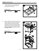
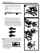
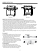
WARNING: IT IS VERY IMPORTANT TO CHECK
AND ENSURE THAT EACH AND EVERY BURNER
IS FULLY ENGAGED WITH THE ADJACENT VALVE
ORIFICE BEFORE COMPLETING STEP 16.
FAILURE TO DO SO MAY
RESULT IN FIRE OR
EXPLOSION, POSSIBLY
CAUSING SERIOUS
INJURY OR DEATH. REFER TO MAINTENANCE
SECTION INSTRUCTIONS TO PROPERLY CHECK
THE ENGAGEMENT.
ASSEMBLY INSTRUCTIONS
15
16
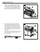
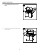
15. Use two M4x12 bolts (BB) to assemble the
side burner valve and the side burner control
knob bezel (H) to the right side burner control
panel (G).
Assemble the ignition wire to the side burner
electrode.
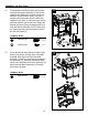
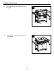
16. Disassemble two M4x10 bolts and two M4
washers that are pre-assembled on the side
burner (F) and use them to assemble the
side burner (F) on the right side burner table
assembly (E). Make sure the side burner orice
is placed into the gas inlet tube of side burner.
Place the side burner cooking grate (D) on the
right side burner table assembly (E). Assemble
the ignition wire to the side burner electrode.
Incorrect
Incorrect
Correct
Hardware Used
BB
M4x12 Bolt
x 2
BB
G
H
BB
AA
DDCC
M6
Spring
Qty. 2
M6
Qty. 2
M4x10
Bolt
Qty. 2
M6x16
Bolt
Qty. 37
Washer
EE
M6
Wingnut
Qty. 2
Washer
FF
Qty. 1
Wrench
F
GL1B
SC U
R
1/2PSI
GL1B
SC U
R
1/2PSI
GL1B
SC U
R
1/2PSI
Incorrect
Incorrect
Correct
D
F
F
GL1B
SC U
R
1/2PSI
GL1B
SC U
R
1/2PSI
GL1B
SC U
R
1/2PSI
Incorrect
Incorrect
Correct
D
F
F
GL1B
SC U
R
1/2PSI
GL1B
SC U
R
1/2PSI
GL1B
SC U
R
1/2PSI
Incorrect
Incorrect
Correct
D
F
F
GL1B
SC U
R
1/2PSI
GL1B
SC U
R
1/2PSI
GL1B
SC U
R
1/2PSI
Incorrect
Incorrect
Correct
D
F
F
E
F
D
E
2 washers
previously
disassembled
2 bolts previously
disassembled