Heavy-Duty Compact Barrel Charcoal Grill MODEL #DGSS443CB-D / DGSS443CB Français p. 19 Español p. 37 ATTACH YOUR RECEIPT HERE Serial Number ________________________________ Purchase Date _________________________________ 70-10-596 Questions, problems, missing parts? Before returning to your retailer, call our customer service department at 1-877-447-4768, 8:00 a.m. – 4:30 p.m. CST, Monday – Friday or email customerservice@ghpgroupinc.com. 1 Rev.
TABLE OF CONTENTS Safety Information ...................................................................................................................... 2 Package Contents ...................................................................................................................... 4 Hardware Contents .................................................................................................................... 5 Preparation ...................................................................
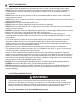
SAFETY INFORMATION • Use caution when assembling and operating this unit to avoid cuts and scrapes from edges. • DO NOT use this product in a manner other than its intended purpose. It is NOT intended for commercial use. It is NOT intended to be installed or used in or on a recreational vehicle and/or boats. • DO NOT store this unit near gasoline or other combustible liquids or where other combustible vapors may be present. • DO NOT use, store or operate this unit in an area accessible to children or pets.
PACKAGE CONTENTS C A A B Y D E X W F H I V A U T G M N K J R S Q L PART A B C D E F G H I J K L M DESCRIPTION Lid Temperature Gauge Smoke Stack Damper Lid Handle Smoke Stack Smoke Stack Gasket Grill Body Side Handle Grease Cup Support Left Leg - Rear Bottom Shelf Left Leg - Front Right Leg - Rear O P QUANTITY 1 1 1 1 1 1 1 1 1 1 1 1 1 PART N I O P Q R S T U V W X Y 4 DESCRIPTION Right Leg - Front Wheel Axle Wheels Offset Smoker Box Support Front Shelf Bracket - Left Front Shelf Bracke
HARDWARE CONTENTS AA BB CC M6 x 12 Bolt M6 Nut M6 Flat Washer Qty. 31 Qty. 28 Qty. 16 DD EE M12 Nut M6 Lock Nut Qty. 2 Qty. 1 FF GG HH M6 x 14 Bolt M5 x 13 Bolt M5 Nut Qty. 1 Qty. 1 Qty. 1 PREPARATION Before beginning assembly of product, make sure all parts are present. Compare parts with package contents list and hardware contents above. If any part is missing or damaged, do not attempt to assemble the product. Contact customer service for replacement parts.
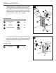
ASSEMBLY INSTRUCTIONS CAUTION: This unit is HEAVY! Do not attempt to handle this unit without assistance! 1. Remove the pre-installed bolt and washer from the left lid hinge on the grill body (G) and slide the lid (A) off the grill body hinges. 1 Pre-installed Hardware A G 2. Attach the left front leg (L) and right front leg (N) using four M6 x 12 bolts (AA), four M6 nuts (BB) and four M6 flat washers (CC) per leg.
ASSEMBLY INSTRUCTIONS 3. Before attaching the rear legs, insert the bottom shelf (K) posts into the holes located on all four legs. WIth the bottom shelf (K) securely in place, attach the left rear leg (J) and right rear leg (M) using four M6 x 12 bolts (AA), four M6 nuts (BB) and four M6 flat washers (CC), per leg. 3 CC BB AA Hardware Used M AA M6 x 12mm Bolt x8 BB M6 Nut x8 CC M6 Flat Washer x8 K J 4.
ASSEMBLY INSTRUCTIONS 5. Attach side handle (H) to the left side of the grill body (G) using four M6 x 12 bolts (AA) and four M6 nuts (BB). 5 H AA G Hardware Used AA M6 x 12mm Bolt x4 BB M6 Nut x4 6. BB Place the smoke stack gasket (F) between the grill body (G) and the smoke stack (E) and attach using four M6 x 12 bolts (AA) and four M6 nuts (BB).
ASSEMBLY INSTRUCTIONS 7. Attach the smoke stack damper (C) using the pre-installed spring and nut. 7 C 8. Insert the end of the grease cup support (I) into the hole located on the bottom of the smoker body (G). Thread the support through the hole until the support is hanging as shown. Note: This grill does not include a container for catching grease or liquids from inside the smoker body.
ASSEMBLY INSTRUCTIONS 9. Attach the right shelf bracket (S) to the grill body (G), using two M6 x 12 bolts (AA) and two M6 nuts (BB), and insert the shelf support wire into the bracket, as shown. Insert the shelf supports into the left shelf bracket (R), before securing the bracket with two M6 x 12 bolts (AA) and two M6 nuts (BB). 9 S G Hardware Used AA M6 x 12mm Bolt x4 BB M6 Nut x4 10.
ASSEMBLY INSTRUCTIONS 11. 12. Attach the lid assembly (A) to the hinges on the grill body (G) using the pre-installed bolt and washer. 11 Attach the side damper plate (V) to the inside of the the access door (W) using one M6 x 12 bolt (AA) and one M6 lock nut (EE). 12 Attach the door latch (U) to the outside of the access door (W) using one M5 x 12 bolt (GG) and one M5 nut (HH).
ASSEMBLY INSTRUCTIONS 13. Screw one M6 x 14 shoulder bolt (FF) into the grill body (G). Attach the access door (W) to the grill body (G) by sliding the hinge rods into the hinge openings on the grill body (G). 13 G Latch the access door (W) by pivoting the door latch (U) onto the M6 x 14 bolt on the grill body (G). W Hardware Used FF 14. M6 x 12mm Bolt x1 FF Install the charcoal grates (X) on the bottom support rails inside the grill body (G).
ASSEMBLY INSTRUCTIONS 15. Attach the offset support bracket (Q) to the right front (N) and rear leg (M) using two M6 x 12 bolts (AA).
OPERATING INSTRUCTIONS BEFORE FIRST USE Remove all hangings or plastic straps, if present. It is important to "season" your grill, prior to cooking food. Seasoning seals the paint and interior of your smoker to enhance flavoring, durability and overall performance. To season your grill, simply use it as you normally would without adding food. You will need to follow all of the lighting and operating procedures in the next few sections of this manual.
CARE AND MAINTENANCE AFTER USE SAFETY AND MAINTENANCE WARNING • Use caution when lifting and moving the unit to avoid strain injuries. Two people are recommended to lift or move the unit. • DO NOT store the unit near gasoline or other combustible liquids or where combustible vapors may be present. Keep the area around the appliance clear and free of combustible materials and vapors. • DO NOT store this appliance in an area accessible to children or pets. Store the appliance in a dry, protected location.
WARRANTY This charcoal grill is warranted against broken or damaged parts at the time of purchase. All parts carry a one (1) year limited warranty. Paint is warranted to be free of defects for 90 days except for rust, which may appear after repeated use. This warranty does not cover damage or issues related to neglect, abuse or modifications to the appliance. Repair labor is not covered. All parts that meet the warranty requirements will be shipped at no charge via the discretion of GHP Group Inc.
REPLACEMENT PARTS LIST For replacement parts, call our customer service department at 1-877-447-4768, 8:00 a.m. – 4:30 p.m. CST, Monday – Friday or email customerservice@ghpgroupinc.com.
REPLACEMENT PARTS LIST 3 2 1 26 25 4 A 5 24 22 6 8 9 23 7 14 13 10 20 18 19 11 12 21 17 A 15 16 70-10-596 Printed in China 18
Barbecue au charbon haute-capacité cylindrique compact MODÈLE NO DGSS443CB-D/ DGSS443CB AGRAFEZ VOTRE FACTURE ICI Numéro de série ________________________________ Date d’achat _________________________________ 70-10-596 Des questions, des problèmes, des pièces manquantes? Avant de retourner chez votre détaillant, appelez notre service à la clientèle au 1 877 447-4768, entre 8 h et 16 h 30 (HNC), du lundi au vendredi ou écrivez à customerservice@ghpgroupinc.com. 19 Rév.
TABLE DES MATIÈRES Informations relatives à la sécurité ............................................................................................. 20 Contenu de l’emballage .............................................................................................................. 22 Quincaillerie fournie .................................................................................................................... 23 Préparation ....................................................................
INFORMATIONS RELATIVES À LA SÉCURITÉ • Ne rangez et n’utilisez PAS le produit dans un endroit accessible aux enfants ou aux animaux. Rangez-le dans un endroit sec et protégé. • Ne laissez PAS l’appareil sans surveillance pendant qu’il est en fonction. • Ne laissez PAS de cendres chaudes sans surveillance tant que le barbecue n’a pas complètement refroidi. • Ne déplacez PAS l’appareil lorsqu’il est en fonction ou que les cendres sont encore chaudes.
CONTENU DE L’EMBALLAGE C A A B Y D E X W F H I V A U T G M N K J R S Q L PIÈCE A B C D E F G H I J K L M DESCRIPTION O P QUANTITÉ Couvercle Jauge de température Clapet d’aération de la cheminée Poignée du couvercle Cheminée Joint de la cheminée Bâti du barbecue Poignée latérale Support du récupérateur de graisse Pied arrière gauche Tablette inférieure Pied avant gauche Pied arrière droit 1 1 1 1 1 1 1 1 1 1 1 1 1 22 PIÈCE DESCRIPTION QUANTITÉ N Pied avant droit O Axe de roue P Rou
QUINCAILLERIE FOURNIE AA BB CC DD EE Boulon M6 x 12 mm Écrou M6 Rondelle plate M6 Écrou M12 Écrou de blocage M6 Qté 31 Qté 28 Qté 16 Qté 2 Qté 1 FF GG Boulon Boulon M6 x 14 mm M5 x 13 mm Qté 1 Qté 1 HH Écrou M5 Qté 1 PRÉPARATION Avant de commencer l’assemblage du produit, assurez-vous que toutes les pièces sont présentes. Comparez les pièces à la liste de contenu de l’emballage et de quincaillerie fournie précédemment.
INSTRUCTIONS D’ASSEMBLAGE M ISE EN GARDE : Cet appareil est LOURD! Ne tentez pas de le manipuler sans aide! 1. Retirez le boulon et la rondelle préinstallés sur la charnière gauche du couvercle du bâti du barbecue (G) et glissez le couvercle (A) hors des charnières du bâti du barbecue. 2. Fixez les pieds avant gauche (L) et droit (N) à l’aide de quatre (4) boulons M6 x 12 mm (AA), de quatre (4) écrous M6 (BB) et de quatre (4) rondelles plates M6 (CC) par pied.
INSTRUCTIONS D’ASSEMBLAGE 3. Avant de fixer les pieds arrière, insérez les tenons de la tablette inférieure (K) dans les trous situés sur les quatre (4) pieds. Une fois la tablette inférieure (K) bien en place, fixez les pieds arrière gauche (J) et droit (M) à l’aide de quatre (4) boulons M6 x 12 mm (AA), de quatre (4) écrous M6 (BB) et de quatre (4) rondelles plates M6 (CC) par pied. 3 CC BB AA Matériel utilisé M AA Boulon M6 x 12 mm x8 BB Écrou M6 x8 CC Rondelle plate M6 K x8 J 4.
INSTRUCTIONS D’ASSEMBLAGE 5. Fixez la poignée latérale (H) au côté gauche du bâti du barbecue (G) à l’aide de quatre (4) boulons M6 x 12 mm (AA) et de quatre (4) écrous M6 (BB). 5 H AA G Matériel utilisé AA Boulon M6 x 12 mm x4 BB Écrou M6 x4 BB 6. Placez le joint de la cheminée (F) entre le bâti du barbecue (G) et la cheminée (E) et fixez le tout à l’aide de quatre (4) boulons M6 x 12 mm (AA) et de quatre (4) écrous M6 (BB).
INSTRUCTIONS D’ASSEMBLAGE 7. Fixez le clapet d’aération de la cheminée (C) à l’aide du ressort et de l’écrou préinstallés. 7 C 8. Insérez l’extrémité du support du récupérateur de graisse (I) dans le trou situé au fond du bâti du barbecue (G). Faites glisser le support dans le trou jusqu’à ce qu’il soit suspendu comme illustré. Remarque : Ce barbecue ne comprend pas de contenant pour récupérer la graisse ou les liquides s’écoulant à l’intérieur du bâti du barbecue.
INSTRUCTIONS D’ASSEMBLAGE 9. Fixez le support de tablette de droite (S) au bâti du barbecue (G) à l’aide de deux (2) boulons M6 x 12 mm (AA) et de deux (2) écrous M6 (BB). Insérez les tiges de la tablette dans le support comme illustré. Insérez les tiges de la tablette dans le support de tablette de gauche (R) avant de le fixer à l’aide de deux (2) boulons M6 x 12 mm (AA) et de deux (2) écrous M6 (BB). 9 S G Matériel utilisé AA Boulon M6 x 12 mm x4 BB Écrou M6 x4 R BB 10.
INSTRUCTIONS D’ASSEMBLAGE 11. Fixez l’assemblage du couvercle (A) aux charnières du bâti du barbecue (G) à l’aide du boulon et de la rondelle préinstallés. 11 12. Fixez le registre latéral (V) à l’intérieur de la porte d’accès (W) à l’aide d’un (1) boulon M6 x 12 mm (AA) et d’un (1) écrou de blocage M6 (EE). 12 Fixez le loquet de la porte (U) à l’extérieur de la porte d’accès (W) à l’aide d’un (1) boulon M5 x 12 mm (GG) et d’un (1) écrou M5 (HH).
INSTRUCTIONS D’ASSEMBLAGE 13. Vissez un (1) boulon à épaulement M6 x 14 mm (FF) dans le bâti du barbecue (G). Fixez la porte d’accès (W) au bâti du barbecue (G) en faisant glisser les tiges de la charnière dans les trous de la charnière du bâti du barbecue (G). 13 G W Verrouillez la porte d’accès (W) en pivotant le loquet de la porte (U) sur le boulon M6 x 14 mm du bâti du barbecue (G). Matériel utilisé FF Boulon M6 x 12 mm FF x1 14.
INSTRUCTIONS D’ASSEMBLAGE 15. Fixez le support du fumoir décalé (Q) aux pieds droits avant (N) et arrière (M) à l’aide de deux (2) boulons M6 x 12 mm (AA). Remarque : Ce support sert à soutenir la chambre de combustion du fumoir décalé Dyna‑Glo DGSS287CB-D (vendu séparément).
INSTRUCTIONS DE FONCTIONNEMENT AVANT LA PREMIÈRE UTILISATION Retirez tous les emballages et toutes les attaches de plastique, le cas échéant. Avant la cuisson des aliments, il est important de culotter le barbecue. Le culottage permet de sceller la peinture et l’intérieur de l’appareil pour améliorer le goût des aliments, en plus d’augmenter la durabilité et la performance globale. Pour culotter le barbecue, utilisez-le comme vous le feriez normalement, mais en ne faisant cuire aucun aliment.
ENTRETIEN ET MAINTENANCE SÉCURITÉ ET ENTRETIEN APRÈS USAGE AVERTISSEMENT • Soyez prudent lorsque vous soulevez et déplacez l’appareil afin d’éviter les douleurs et les blessures. Il est conseillé de s’y prendre à deux pour le soulever ou le déplacer. • N’entreposez PAS l’appareil près d’essence ou d’autres liquides combustibles, ni dans des endroits où des vapeurs combustibles peuvent être présentes. Maintenez la zone entourant l’appareil propre et libre de tout matériau ou de toute vapeur combustibles.
GARANTIE Ce barbecue au charbon est garanti contre les pièces brisées ou endommagées au moment de l’achat. Toutes les pièces sont couvertes par une garantie limitée d’un (1) an. La peinture est garantie contre les déauts pour une période de 90 jours, mais n’est pas garantie contre la rouille, qui pourrait apparaître après une utilisation répétée. La garantie ne couvre pas les dommages et les problèmes causés par une négligence, une utilisation abusive ou des modifications apportées à l’appareil.
LISTE DES PIÈCES DE RECHANGE Pour obtenir des pièces de rechange, appelez notre service à la clientèle au 1 877 447-4768, entre 8 h et 16 h 30 (HNC), du lundi au vendredi, ou écrivez à customerservice@ghpgroupinc.com.
LISTE DES PIÈCES DE RECHANGE 3 2 1 26 25 4 A 5 24 22 6 8 9 23 7 14 13 10 20 18 19 11 12 21 17 A 15 16 70-10-596 Imprimé en Chine 36
Resistente Parrilla compacta de tambor a carbón MODELO N.° DGSS443CB-D / DGSS443CB ADJUNTE SU RECIBO AQUÍ Número de serie ________________________________ Fecha de compra ________________________________ 70-10-596 ¿Dudas, problemas, piezas faltantes? Antes de volver a la tienda, llame a nuestro Departamento de Atención al Cliente al 1-877-447-4768, de lunes a viernes de 8:00 a 16:30 (hora central estándar),o escriba a customerservice@ghpgroupinc.com. 37 Rev.
CONTENIDO Información de seguridad ........................................................................................................... 38 Contenido del paquete ............................................................................................................... 40 Herramientas y tornillería ........................................................................................................... 41 Preparación ...............................................................................
INFORMACIÓN DE SEGURIDAD •N O utilice ni guarde esta unidad en un área a la que podrían acceder niños o mascotas. Guarde esta unidad en un lugar seco y protegido. • NO deje desatendida la unidad mientras esté en uso. • NO deje desatendidas las cenizas calientes hasta que la unidad se enfríe completamente. •N O mueva la unidad mientras esté encendida o mientras las cenizas estén calientes. Deje que la unidad se enfríe completamente antes de moverla o guardarla.
CONTENIDO DEL PAQUETE C A A B Y D E X W F H I V A U T G M N K J R S Q L PIEZA A B C D E F G H I J K L M DESCRIPCIÓN Tapa Indicador de temperatura Regulador de tiro de la chimenea Manija de la tapa Chimenea Junta de la chimenea Estructura de la parrilla Manija lateral Soporte de la grasera Pata izquierda: trasera Estante inferior Pata izquierda: frontal Pata derecha: trasera O P CANTIDAD PIEZA DESCRIPCIÓN CANTIDAD 1 1 1 N O P Q R Pata derecha: frontal Eje de las ruedas Ruedas Sopo
HERRAMIENTAS Y TORNILLERÍA AA BB CC DD EE FF GG HH Perno M6 × 12 Tuerca M6 Arandela plana M6 Tuerca M12 Contratuerca M6 Perno M6 × 14 Perno M5 × 13 Tuerca M5 Cant. 16 Cant. 2 Cant. 1 Cant. 1 Cant. 1 Cant. 1 Cant. 31 Cant. 28 PREPARACIÓN Antes de comenzar a ensamblar el producto, asegúrese de tener todas las piezas. Compare las piezas con la lista del contenido del paquete, y con las herramientas y tornillería que figuran más arriba.
INSTRUCCIONES DE ENSAMBLAJE P RECAUCIÓN: Esta unidad es PESADA. No intente manipular esta unidad sin ayuda. 1. Quite el perno y la arandela preinstalados de la bisagra izquierda de la estructura de la parrilla (G) y deslice la tapa (A) hacia afuera de las bisagras de la estructura de la parrilla. 2. Fije la pata frontal izquierda (L) y la pata frontal derecha (N) utilizando cuatro pernos M6 × 12 (AA), cuatro tuercas M6 (BB) y cuatro arandelas planas M6 (CC) en cada pata.
INSTRUCCIONES DE ENSAMBLAJE 3. Antes de colocar las patas traseras, inserte los pasantes del estante inferior (K) en los orificios ubicados en las cuatro patas. Con el estante inferior (K) colocado firmemente en su lugar, fije la pata trasera izquierda (J) y la pata trasera derecha (M) utilizando cuatro pernos M6 × 12 (AA), cuatro tuercas M6 (BB) y cuatro arandelas planas M6 (CC) en cada pata.
INSTRUCCIONES DE ENSAMBLAJE 5. Instale la manija lateral (H) en el lado izquierdo de la estructura de la parrilla (G) utilizando cuatro pernos M6 × 12 (AA) y cuatro tuercas M6 (BB). 5 H AA G Herramientas y tornillería utilizadas AA Perno M6 × 12 mm ×4 BB Tuerca M6 ×4 BB 6. Coloque la junta de la chimenea (F) entre la estructura de la parrilla (G) y la chimenea (E), y fíjela utilizando cuatro pernos M6 × 12 (AA) y cuatro tuercas M6 (BB).
INSTRUCCIONES DE ENSAMBLAJE 7. Coloque el regulador de tiro de la chimenea (C) utilizando el resorte y la tuerca preinstalados. 7 C 8. Inserte el extremo del soporte de la grasera (I) en el orificio ubicado en la parte inferior de la estructura del ahumador (G). Enrosque el soporte en el orificio hasta que quede colgando como se muestra. Nota: Esta parrilla no incluye un contenedor para recolectar grasa o líquidos del interior de la estructura del ahumador.
INSTRUCCIONES DE ENSAMBLAJE 9. Fije la abrazadera derecha del estante (S) a la estructura de la parrilla (G) utilizando dos pernos M6 × 12 (AA) y dos tuercas M6 (BB), e inserte el soporte del estante en la abrazadera, como se muestra. Inserte los soportes del estante en la abrazadera izquierda del estante (R), antes de fijar la abrazadera con dos pernos M6 × 12 (AA) y dos tuercas M6 (BB). 9 S G Herramientas y tornillería utilizadas AA Perno M6 × 12 mm ×4 BB Tuerca M6 ×4 R BB 10.
INSTRUCCIONES DE ENSAMBLAJE 11. Fije el conjunto de la tapa (A) a las bisagras de la estructura de la parrilla (G) utilizando el perno y la arandela preinstalados. 11 12. Fije el plato regulador de tiro lateral (V) a la parte interior de la puerta de acceso (W) utilizando un perno M6 × 12 (AA) y una contratuerca M6 (EE). 12 Fije el cerrojo de la puerta (U) a la parte exterior de la puerta de acceso (W) utilizando un perno M5 × 12 (GG) y una tuerca M5 (HH).
INSTRUCCIONES DE ENSAMBLAJE 13. Atornille un perno de tope M6 x 14 (FF) en la estructura de la parrilla (G). Fije la puerta de acceso (W) a la estructura de la parrilla (G) deslizando las varillas de la bisagra dentro de las aberturas de la bisagra en la estructura de la parrilla (G). 13 G W Cierre el cerrojo de la puerta de acceso (W) haciendo girar el cerrojo de la puerta (U) en el perno M6 x 14 de la estructura de la parrilla (G).
INSTRUCCIONES DE ENSAMBLAJE 15. Fije la abrazadera de soporte del conjunto lateral (Q) a la pata frontal (N) y la pata trasera (M) utilizando dos pernos M6 × 12 (AA). Nota: Esta abrazadera se utiliza para sostener el ahumador Dyna-Glo modelo DGSS287CB-D (se vende por separado).
INSTRUCCIONES DE FUNCIONAMIENTO ANTES DE UTILIZAR LA UNIDAD POR PRIMERA VEZ Quite todas las presillas o las fajas de plástico, si están presentes. Es importante "curar" la parrilla antes de cocinar alimentos. Este proceso sella la pintura y el interior del ahumador para mejorar el sabor, la durabilidad y el rendimiento en general. Para curar la parrilla, simplemente utilícela como lo haría normalmente, pero sin agregar alimentos.
CUIDADO Y MANTENIMIENTO SEGURIDAD Y MANTENIMIENTO DESPUÉS DEL USO ADVERTENCIA • Tenga precaución al levantar y mover la unidad para evitar lesiones por esfuerzo. Se recomienda levantar o mover la unidad entre dos personas. •N O guarde la unidad cerca de gasolina u otros líquidos combustibles o donde podría haber vapores combustibles. Asegúrese de que no haya materiales ni vapores combustibles en el área donde se encuentra el artefacto.
GARANTÍA Esta parrilla a carbón está garantizada contra piezas rotas o dañadas en el momento de la compra. Todas las piezas tienen una garantía limitada por un (1) año. La pintura tiene una garantía contra defectos por 90 días, a excepción del óxido, que podría aparecer después de varios usos. Esta garantía no cubre daños o problemas relacionados con la negligencia, el uso indebido o modificaciones realizadas al artefacto. El trabajo de reparación no está cubierto.
LISTA DE PIEZAS DE REPUESTO Para obtener piezas de repuesto, llame a nuestro Departamento de Atención al Cliente al 1-877-447-4768, de lunes a viernes de 8:00 a 16:30 (hora central estándar), o escriba a customerservice@ghpgroupinc.com.
LISTA DE PIEZAS DE REPUESTO 3 2 1 26 25 4 A 5 24 22 6 8 9 23 7 14 13 10 20 18 19 11 12 21 17 A 15 16 70-10-596 Impreso en China 54