VENT-FREE BLUE FLAME GAS ICE HOUSE HEATER MODEL # IBF10PMDG IBF10PTDG C C US US ANS Z21.11.2-2013 Gas Fired Room Heaters Volume II - Unvented Room Heaters WARNING: This appliance is equipped for propane gas. Field conversion is not permitted. CSA IR 4.98 U.S. Gas Fired Room Heaters For Recreational and Commercial Use. WARNING: IF THE INFORMATION IN THIS MANUAL IS NOT FOLLOWED EXACTLY, A FIRE OR EXPLOSION MAY RESULT CAUSING PROPERTY DAMAGE, PERSONAL INJURY OR LOSS OF LIFE.
TABLE OF CONTENTS Important Safety Information ............................................................................................................3 Product Features............................................................................................................................... 6 Air For Combustion and Ventilation................................................................................................... 8 Installation.............................................................
IMPORTANT SAFETY INFORMATION IMPORTANT: Read this owner’s manual carefully and completely before trying to assemble, operate, or service this heater. Improper use of this heater can cause serious injury or death from burns, fire, explosion, electrical shock, and carbon monoxide poisoning. Installation and repair should be done by a qualified service person. The appliance should be inspected before use and at least annually by a professional service person.
SAFETY INFORMATION WARNING: Do not use any accessories not approved for use with this heater. WARNING This product and the fuels used to operate this product (liquid propane or natural gas), and the products of combustion of such fuels, can expose you to chemicals including benzene, which is known to the State of California to cause cancer and reproductive harm. For more information go to www.p65Warnings.ca.gov 1. Do not place Propane/LP supply tank(s) inside any structure.
PRODUCT FEATURES SAFETY PILOT This heater has a pilot with an Oxygen Depletion Sensing (ODS) safety shutoff system. The ODS/pilot shuts off the heater if there is not enough fresh air and cuts off main burner gas in the event of flame out. ELECTRONIC PUSH BUTTON IGNITION SYSTEM This heater is equipped with an electronic push button ignition system. This system requires one AAA battery (provided).
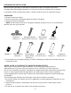
PREPARING FOR INSTALLATION Before beginning assembly or operation of the product, make sure all parts are present. Compare parts with package contents list. If any part is missing or damaged, do not attempt to assemble, install or operate the product. Contact customer service for replacement parts. UNPACKING 1. Remove heater from carton. 2. Remove all protective packaging applied to heater for shipping 3. Verify all contents are present. NOTE: Wood Screw (ST4.8*45-16), Expansion Bracket Screw(ST4.
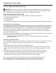
PREPARING FOR INSTALLATION AIR FOR COMBUSTION AND VENTILATION CAUTION: This heater shall not be installed in a room or space unless the required volume of indoor combustion air is provided by the method described in the National Fuel Gas Code, ANSI Z223.1/NFPA54, the International Fuel Gas Code, or applicable local codes. PRODUCING ADEQUATE VENTILATION All spaces in homes fall into one of the three following ventilation classifications: 1. Unusually Tight Construction 2. Unconfined Space 3.
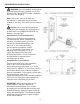
PREPARING FOR INSTALLATION DETERMINING FRESH-AIR FLOW FOR HEATER LOCATION Determining if You Have a Confined or Unconfined Space Use this worksheet to determine if you have a confined or unconfined space. Space: Includes the room in which you will install heater plus any adjoining rooms with doorless passageways or ventilation grills between the rooms. 1. Determine the volume of the space Length × Width × Height = cu. ft. (volume of space) Example: Space size 20 ft. (length) × 16 ft.(width) × 8 ft.
PREPARING FOR INSTALLATION WARNING: If the recreational or commercial enclosure does not have a window or roof vent, DO NOT USE THIS HEATER inside." Ventilation Air From Inside Building. Note: This heater can only be used in a recreational or commercial enclosure with a window or roof vent. This heater is not for outdoor use." Caution: When used without adequate combustion and ventilation air, this heater may give off excessive CARBON MONOXIDE, an odorless, poisonous gas.
INSTALLATION NOTICE: This heater is intended for use as supplemental heat. Use this heater along with your primary heating system. Do not install this heater as your primary heat source. WARNING: A qualified technician must install heater. Follow all local codes. WARNING: Maintain the minimum clearances. If possible, provide greater clearances from the floor, ceiling, and adjoining wall than required. CAUTION: This heater creates warm air currents. These currents move heat to wall surfaces next to heater.
INSTALLATION INSTALLING IGNITOR BATTERY • Battery is included. • Unscrew ignitor cap and insert included battery negative (flat) side down (See Fig. 7). Replace Ignitor cap. • Be sure to observe proper polarity (+/-) when installing or replacing the battery. Damage due to improper battery installation may void the warranty on the product. • Install/replace the battery according to the type and quantity stated in table below. • Remove battery when depleted.
INSTALLATION Fig. 12- Fan Wiring Diagram Caution: Label all wires prior to disconnection when servicing controls. Wiring errors can cause improper and dangerous operation. Fig. 11 - Operating Fan MAN If any of the original wire as supplied with the appliance must be replaced, it must be replaced with a wire of at least a 60°C temperature rating. AUTO Fan Rocker Switch LOCATING HEATER This heater is designed to be mounted on a wall. For convenience and efficiency, install heater: 1.
INSTALLATION Methods For Attaching Mounting Bracket To Wall Use only the last hole on each end of mounting bracket to attach bracket to wall. Attach mounting bracket to a wall only in one of two ways: 1. Attaching to wall stud: This method provides the strongest hold. Insert wood screws (ST.8*45-16) through mounting bracket and into wall studs. 2.
INSTALLATION Attaching to Expansion Bracket Method For attaching mounting bracket to hollow walls (wall areas between studs) or solid walls (concrete or masonry): Fig. 14 - Folding the Expansion Bracket 1. Drill holes at marked locations using 5/16-inch drill bit. For solid walls (concrete or masonry), drill at least 1 inch deep. 2. Fold wall expansion bracket as shown in (See Fig. 14). 3. Insert wall expansion bracket (wings first) into hole. Tap expansion bracket flush to wall. Fig.
INSTALLATION CONNECTING TO GAS SUPPLY USING RIGID PIPE WARNING: A qualified service technician must connect heater to gas supply. Follow all local codes. WARNING: Do not overtighten gas connections. CAUTION: Check your gas line pressure before connecting heater to gas line. Gas line pressure must be a minimum 11" WC for LP with a max pressure of 14"WC. If gas line pressure is higher, heater regulator damage could occur. CAUTION: Never connect heater directly to an LP supply.
INSTALLATION CONNECTING TO GAS SUPPLY USING GAS HOSE ASSEMBLY WARNING: A qualified service technician must connect heater to gas supply. Follow all local codes. CAUTION: Avoid damage to regulator. Hold gas regulator with wrench when connecting into gas piping and/or fittings. CAUTION: Use pipe joint sealant that is resistant to gas (Propane or Natural Gas). WARNING: Do not overtighten gas connections.
INSTALLATION CONNECTING GAS CYLINDER The propane gas supply cylinder to be used must be constructed and marked in accordance with the Specifications for LP Gas Cylinders of the U.S. Department of Transportation (D.O.T.) or the National Standard of Canada, CAN/CSA-B339, Cylinders, Spheres and Tubes for Transportation of Dangerous Goods; and Commission, as applicable; and provided with a listed overfilling prevention device. Use only 20-pound cylinders (height: 18.11 inches, tank diameter: 9.
INSTALLATION WARNING: A qualified service technician must connect heater to gas supply. Follow all local codes. CAUTION: Avoid damage to regulator. Hold gas regulator with wrench when connecting into gas piping and/or fittings. CAUTION: Use pipe joint sealant that is resistant to gas (Propane or Natural Gas). WARNING: Do not overtighten gas connections. CONNECTING THE LP TANK 1. The knob on the LP tank must be closed. Make sure that the knob is turned clockwise to a full stop.
INSTALLATION CHECKING FOR LEAKS After all connections are made, check all connections and fittings on the LP gas tank valve, gas hose and regulator for leaks with a water and soap solution. To prevent fire or explosion while testing for a leak: • Always perform leak test prior to lighting the heater. • Do not smoke while testing for a leak. • Always perform leak tests outdoors in a well-ventilated area. • Do not use any source of flame while testing for leaks.
OPERATION FOR YOUR SAFETY READ BEFORE LIGHTING WARNING: If you do not follow these instructions exactly, a fire or explosion may result causing property damage, personal injury or loss of life. A. This appliance has a pilot which must be lighted using the Ignitor. When lighting the pilot, follow these instructions exactly. B. BEFORE LIGHTING smell all around the appliance area for gas. Be sure to smell next to the floor because some gas is heavier than air and will settle on the floor.
OPERATION LIGHTING INSTRUCTIONS If the control knob does not pop up when released, stop and immediately and call your service technician or gas supplier. 8. Turn on all electric power to the appliance. 9. Turn control knob counter clockwise to the desired setting. OFF P IL OT 1 2 3 THERMOSTAT GAS CONTROL 1. STOP! Read the safety information on the previous page. 2. Turn off all electric power to the appliance. 3. Turn control knob clockwise to "OFF" position. (See Fig. 22b) 4.
OPERATION 2 3 Manual 4 5 OFF P IL 1 The thermostat used on this heater senses the room temperature. At times the room may exceed the set temperature. If so, the burner will shut off. The burner will cycle back on when room temperature drops below the set temperature. The control knob can be set to any comfort level between "HIGH" (5) and "LOW"(1) (See Fig. 25).
OPERATION BURNER FLAME PATTERN Fig. 28 shows a correct burner flame pattern. Fig. 29 shows an incorrect burner flame pattern with lifting, and excessive flame height. If burner flame is incorrect: • turn heater off (see “To Turn Off Gas to Appliance”, page 21). • see Troubleshooting, pages 25 - 28. Fig. 28 - Correct/Normal Flame Pattern with short flames with Control Knob Set to High Flame (5) Fig.
CARE AND MAINTENANCE NOTE: Before servicing you will need to remove the front panel of the heater. Fig. 30 - Front Panel Removal There are 4 Philips head screws, 2 on the left side and 2 on the right, securing the front panel to the heater (See Fig. 30). Always allow the unit to cool for at least thirty minutes before attempting to remove the front panel. WARNING: Turn off heater, unplug electrical cord and let cool before servicing.
TROUBLESHOOTING WARNING: If you smell gas: • Shut off gas supply. • Do not try to light any appliance. • Do not touch any electrical switch; do not use any phone in your building. • Immediately call your gas supplier from a neighbor’s phone. Follow the gas supplier’s instructions. • If you cannot reach your gas supplier, call the fire department. IMPORTANT: Operating heater where impurities in air exist may create odors.
TROUBLESHOOTING PROBLEM POSSIBLE CAUSE CORRECTIVE ACTION 1. Control knob is not fully ODS/pilot lights pressed in. but flame goes out 2. Control knob is not pressed when control knob is in long enough. released. 3. Equipment shutoff valve is not fully open. 4. Thermocouple connection is loose. 5. Thermocouple damaged. 6. Control valve damaged. 7. Inlet gas pressure is too high 1. Press in control knob fully. 2. After ODS/pilot lights, keep control knob pressed in 30-60 seconds. 3.
TROUBLESHOOTING PROBLEM POSSIBLE CAUSE CORRECTIVE ACTION White powder residue forming within burner box or on adjacent walls or furniture. 1. When heated, the vapors from furniture polish, wax, carpet cleaners, etc., turn into white powder residue. 1. Turn heater off when using furniture polish, wax, carpet cleaner or similar products. Heater produces unwanted odors. 1. Heater is burning vapors from paint, hair spray, glues, etc. See IMPORTANT statement, page 25. 2. Gas leak.
TROUBLESHOOTING PROBLEM POSSIBLE CAUSE CORRECTIVE ACTION Fan is not spinning. (Select Models) 1. There is no power to the fan. 1. Verify fan is plugged in and set to "MAN" or "AUTO". 2. Allow 5-10 minutes for fan to engage. 3. Replace fan. 2. Fan is set to "AUTO". 3. Fan motor is bad. Fan is making a loud noise. (Select Models) 1. Fan housing or blades are dirty. 2. Fan rotation is blocked. 3. Defective fan. 28 1. See "Cleaning Fan", page 24. 2. Verify wiring is not in fan path. 3. Replace fan.
REPLACEMENT PARTS LIST For replacement parts, call our customer service department at 1-877-447-4768, 8:30 a.m. –4:30 p.m., CST, Monday – Friday. WARNING: Only use genuine replacement parts from the GHP Group, Inc. Using any parts other than the original replacement parts may result in property damage, personal injury or even death. 12 4 11 5 10 6 2 8 3 9 7 1 16 13 ITEM No. DESCRIPTION QTY PART NO.
30
WARRANTY 1. not be covered by this warranty, nor shall the LIMITED WARRANTY: The manufacturer warrants that your new product is free This limited warranty is extended to the original retail purchaser of this Forced Air/Convection/Radiant Heater and warrants againstfor any same. manufacturer assume responsibility from manufacturing and material defects for a period of defect in materials and workmanship for a period of one (1) year from the date of retail sale. GHP Group, Inc.
WARRANTY REGISTRATION IMPORTANT: We urge you to fill out your warranty registration card within fourteen (14) days of date of purchase. You can also register your warranty on the internet at www.ghpgroupinc.com. Complete the entire serial number. Retain this portion of the card for your records. GHP Group, Inc. 6440 W Howard GHP Group, Inc. St Niles, IL 60714-3302 GHP 8280 Austin Ave. Morton Grove, IL 60053-3207 Tel: (877) 447-4768 www.ghpgroupinc.com Tel: (877) 447-4768 www.ghpgroupinc.
CALEFACTOR DE PARED LLAMA AZUL CASA DE HEILO A GAS DE TIRO NATURAL NÚM. DE MODELO IBF10PMDG IBF10PTDG C C US US ANS Z21.11.2-2013 ADVERTENCIA: Este aparato está equipado para gas propano. No se permite la conversión. Calentadores de habitación accionados por gas Volumen II - Calentadores de habitación no ventiladas. CSA IR 4.98 U.S. Calentadores de habitación accionados por recreativo y uso comercial.
TABLA DE CONTENIDO Información de seguridad importante................................................................................................3 Características del producto.............................................................................................................. 6 Aire para la combustión y ventilación................................................................................................ 8 Instalación........................................................................
INFORMACIÓN DE SEGURIDAD IMPORTANTE IMPORTANTE: Por favor, lea cuidadosa y completamente este manual del propietario antes de intentar ensamblar, operar o darle servicio a este calefactor. El uso inapropiado de este calefactor puede causar lesiones graves o la muerte por quemaduras, incendio, explosión, choque eléctrico y envenenamiento por monóxido de carbono. La instalación y reparación serán hechos solamente por una persona de servicio calificada.
INFORMACIÓN DE SEGURIDAD ADVERTENCIA: No use ningún accesorio no aprobado para uso con este calefactor. ADVERTENCIA Este producto y los combustibles utilizados para poner en funcionamiento este producto (gas natural o propano líquido), y los productos de la combustión de tales combustibles, pueden exponerlo a sustancias químicas como el benceno que, según el estado de California puede provocar cáncer y daños reproductivos. Para obtener más información, visite www.p65Warnings.ca.gov 1.
CARACTERÍSTICAS DEL PRODUCTO PILOTO DE SEGURIDAD Este calefactor tiene un piloto con un sistema de apagado de seguridad de Detección de disminución de oxígeno (ODS). El ODS/piloto apaga el calefactor si no hay suficiente aire fresco y corta el gas del quemador principal en el caso de que la llama se apague. SISTEMA DE IGNICIÓN ELECTRÓNICA DE BOTÓN DE PRESIÓN Este calefactor está equipado con un sistema de ignición electrónica de botón de presión. Este sistema requiere una batería AAA (proporcionada).
PREPARACIÓN PARA LA INSTALACIÓN Antes de comenzar a ensamblar u operar este producto, asegúrese de que todas las piezas estén presentes. Compare las piezas con la lista de contenido del paquete. Si hace falta alguna pieza o se encuentra dañada, no intente ensamblar, instalar u operar el producto. Póngase en contacto con servicio al cliente para las piezas de reemplazo. DESEMPAQUE 1. Retire el calefactor de la caja. 2. Retire todo el empaque protector aplicado al calefactor para envío. 3.
PREPARACIÓN PARA LA INSTALACIÓN AIRE PARA LA COMBUSTIÓN Y VENTILACIÓN PRECAUCIÓN: Este calefactor no deberá ser instalado en una habitación o espacio a menos que el volumen requerido de aire de combustión de interiores sea proporcionado por el método descrito en el Código Nacional de Gas Combustible, ANSI Z223.1/NFPA54, el Código Internacional de Gas Combustible, o códigos locales aplicables.
PREPARACIÓN PARA LA INSTALACIÓN DETERMINACIÓN DEL FLUJO DE AIRE FRESCO A LA UBICACIÓN DEL CALEFACTOR Determinación de si tiene un espacio confinado o no confinado Use esta hoja de cálculo para determinar si tiene un espacio confinado o no confinado. Espacio: Incluye la habitación en la cual instalará el calefactor más cualquier habitación contigua a pasillos sin puertas o rejillas de ventilación entre las habitaciones. 1.
PREPARACIÓN PARA LA INSTALACIÓN ADVERTENCIA : Si el área recreacional o comercial no tiene una ventana o conducto de techo, NO UTILIZAR EL CALENTADOR dentro del lugar Fig. 1 - Rejillas de ventilación en habitación contigua, Opción 1 Nota: Este calentador sólo puede ser usado dentro de un área recreacional o comercial que tenga una ventana o conducto de techo. Este calentador no es de uso exterior.
INSTALACIÓN AVISO: Este calefactor está diseñado para ser usado como calor complementario. Use este calefactor junto con su sistema de calefacción primario. No instale este calefactor como su fuente primaria de calor. ADVERTENCIA: Un técnico calificado debe instalar el calefactor. Siga todos los códigos locales. ADVERTENCIA: Mantenga los espacios libres mínimos. De ser posible, proporcione espacios libres más grandes que los requeridos desde el piso, techo y pared contigua.
INSTALACIÓN DE LA BATERÍA DEL ENCENDEDOR • La batería está incluida. • Quite la tapa del encendedor e inserte la batería incluida con el negativo (plano) hacia abajo (Ver Fig. 7). Vuelva a colocar la tapa del encendedor. Fig. 7 - Instalación de la batería del • Asegúrese de respetar la polaridad correcta (+/-) cuando insta le o vuelva a instalar la batería Los daños debidos a una insta encendedor lación inapropiada de la batería puede anular la garantía del producto.
INSTALACIÓN Fig. 12- Diagrama del cableado del ventilador Cuidado: Etiquete todos los alambres antes de desconectar cuando haga el mantenimiento a los controles. Errores de cableado puede ocasionar que el funcionamiento del aparato sea inapropiado y peligroso. Fig. 11 - Ventilador de operación MAN Si cualquiera de los alambres originales que vienen con el aparato deben ser reemplazados, deben reemplazarse con un alambre que tenga una clasificación de temperatura de por lo menos 60°C.
INSTALACIÓN Métodos para instalar el soporte de montaje a la pared Use solamente el último agujero en cada extremo del soporte de montaje para instalar el soporte en la pared. Inserte los tornillos para madera (ST4.8*45-16) a través del soporte de montaje y en montantes de la pared . 1. Instalación en soporte de expansión: Este método proporciona la sujeción más fuerte. Inserte los tornillos de montaje a través del soporte de montaje y en los montantes de pared. 2.
INSTALACIÓN Instalación con el método de Soporte de expansión Para instalar el soporte de montaje a paredes huecas (áreas de la pared entre montantes) o paredes sólidas (concreto o mampostería): Fig. 14 - Cómo doblar el soporte de expansión 1. Perfore agujeros en lugares marcados usando una broca de 5/16 pulgadas. Para paredes sólidas (concreto o mampostería), perfore al menos 1 pulgada de profundidad. 2. Doble soporte de expansión como se muestra en (Ver Fig. 14). 3.
INSTALACIÓN CONEXIÓN AL SUMINISTRO DE GAS MEDIANTE TUBERÍA RÍGIDA ADVERTENCIA: Un técnico de servicio calificado debe conectar el calefactor al suministro de gas. Siga todos los códigos locales. ADVERTENCIA: No apriete demasiado las conexiones de gas. PRECAUCIÓN: Revise la presión de la línea del gas antes de conectar el calefactor a la línea de gas. La presión de línea de gas debe ser de un mínimo de 11" WC para PL con una presión máxima de 14" WC.
INSTALACIÓN ADVERTENCIA: Un técnico de servicio calificado debe conectar el calefactor al suministro de gas. Siga todos los códigos locales. PRECAUCIÓN: Evite dañar el regulador. Sostenga el regulador de gas con una llave cuando lo esté conectando a la tubería de gas y/o accesorios. PRECAUCIÓN: Use sellador de juntas de tubo que sea resistente al gas (Propano o gas natural). ADVERTENCIA: No apriete demasiado las conexiones de gas.
INSTALACIÓN CUIDADO: • El cilindro de gas LP utilizado con este aparato debe ser: a) Construido y marcado de acuerdo con las especificaciones para los cilindros de gas LP del Departamento de Transporte de los Estados Unidos (D.O.T.) o el Estándar Nacional de Canadá,CAN/CSA-B339, Cilindros, Esferas y Tubos para el Transporte de Productos Peligrosos; y Comisión, si fuese aplicable; y (b) Proporcionado con un dispositivo licenciado de prevención de sobrecarga.
INSTALACIÓN CUIDADO a. No almacenar un cilindro de gas LP adicional debajo o cerca de este aparato. b. Nunca llene el cilindro a más del 80 por ciento lleno. c. Si la información en los puntos (a) y (b) no son seguidos con exactitud, un incendio causan do muerte o heridas graves puede ocurrir. CONECTANDO EL TANQUE LP 1. La perilla del tanque LP debe estar cerrada. Asegúrese de que la perilla esté volteada en sentido horario hasta detenerse.
INSTALACIÓN REVISANDO FUGAS Una vez que se hayan realizado todas las conexiones, revise con una disolución de agua y jabón todas las conexiones y accesorios en la válvula de tanque de gas LP, la manguera de gas y en el regulador para determinar si hay fuga. Para prevenir incendios o explosiones mientras se revisa si hay fuga: • Siempre realizar una revisión de fuga antes de prender el calentador. • No fumar mientras está revisando si existe alguna fuga.
OPERACIÓN PARA SU SEGURIDAD, LEA ANTES DE ENCENDER ADVERTENCIA: Si no sigue estas instrucciones con exactitud, puede resultar un incendio o explosión ocasionando daños a la propiedad, lesiones personales o la muerte. A. Este aparato tiene un piloto que debe ser encendido con el encendedor. Cuando encienda el piloto, siga estas instrucciones con exactitud. B. ANTES DE ENCENDER huela todo alrededor del área del aparato en busca de gas.
OPERACIÓN INSTRUCCIONES DE ENCENDIDO Si la perilla de control no salta cuando se suelte, pare y llame de inmediato a su técnico de servicio o al proveedor de gas. OT Fig. 22b 1 4 5 FF 3 PILOT 2 O Nota: Si el piloto se apaga repita los pasos 3 al 7. Espere (1) minuto antes de intentar encender el piloto de nuevo. Si después de varios intentos el piloto todavía se apaga, gire la perilla de control hacia la derecha a la posición “OFF” y llame a un técnico de servicio calificado o al proveedor de gas.
OPERACIÓN OPERACIÓN DEL CONTROL TERMOSTÁTICO (MODELOS SELECCIONADOS) Termostático OT 2 3 4 5 OFF P IL 1 El termostato usado en este calefactor detecta la temperatura ambiente. A veces, la temperatura ambiente puede ser mayor que la temperatura de ajuste. Si eso ocurre, el calefactor se apagará. El quemador se activará cuando la temperatura ambiente caiga abajo de la temperatura de ajuste. La perilla de control se puede ajustar a cualquier nivel de comodidad entre "HIGH" (5) y "LOW" (1) (Ver Fig. 25).
OPERACIÓN PATRÓN DE LA LLAMA DEL QUEMADOR La Fig. 28 muestra un patrón correcto de la llama del quemador. La Fig. 29 muestra un patrón incorrecto de la llama del quemador con altura de llama excesiva que se levanta. Si la llama del quemador es incorrecta: • apague el calefactor (ver "Apagar el gas al aparato," página 21). • ver Resolución de fallas, páginas 23 a 26. Fig. 28 - Patrón correcto/normal con llamas cortas con la perilla de control adjustada a llama alta ( 5 ) Fig.
CUIDADO Y MANTENIMIENTO NOTA: Antes de dar servicio necesitará retirar el panel frontal del calefactor. Hay 4 tornillos Philips, 2 en el lado izquierdo y 2 en el derecho, asegurando el panel frontal al calefactor (Ver Fig. 30). Permita siempre que la unidad se enfríe durante al menos treinta minutos antes de intentar retirar el panel frontal. Fig. 30 - Retiro del panel frontal ADVERTENCIA: Apague el calefactor, desconecte el cable eléctrico y deje enfriar antes de dar servicio.
RESOLUCIÓN DE FALLAS ADVERTENCIA: Si huele gas: • Apague el suministro de gas. • No trate de encender ningún aparato. • No toque ningún interruptor eléctrico; no use ningún teléfono en su edificio. • Llame de inmediato a su proveedor de gas del teléfono de un vecino. Siga las instrucciones del proveedor de gas. • Si no puede contactar a su proveedor de gas, llame al Cuerpo de Bomberos. IMPORTANTE: La operación del calentador donde existan impurezas en el aire puede crear malos olores.
RESOLUCIÓN DE FALLAS PROBLEMA El ODS/piloto enciende pero la llama se apaga cuando la perilla de control se suelta. CAUSA POSIBLE ACCIÓN CORRECTIVA 1. La perilla de control no está completamente presionada. 2. La perilla de control no está presionada suficiente tiempo. 3. La válvula de cierre del equipo no está completamente abierta. 4. La conexión del termopar está floja. 5. Termopar dañado. 6. Válvula de control dañada. 7. La presión del gas de entrada es demasiado alto. 1.
RESOLUCIÓN DE FALLAS PROBLEMA CAUSA POSIBLE ACCIÓN CORRECTIVA Residuo de polvo 1. Cuando se calientan, los vablanco que se forpores del pulidor de muebles, ma dentro de la caja cera, limpiadores de alfombra, del quemador o en ect. se convierten en residuo paredes adyacentes o de polvo blanco. muebles. 1. Apague el calefactor cuando use pulidor de mueble, cera, limpiador de alfombra o productos similares. 1. El calefactor está quemando vapores de pintura, spray para el cabello, pegamentos, etc.
RESOLUCIÓN DE FALLAS PROBLEMA CAUSA POSIBLE ACCIÓN CORRECTIVA El ventilador no está girando (Modelos seleccionados). 1. No hay energía en el ventilador. 1. Compruebe que el ventilador esté conectado y ajustado a "MAN" o "AUTO". 2. Espere de 5 a 10 minutos para que el ventilador se enganche. 3. Reemplace el ventilador. 2. El ventilador está ajustado a "AUTO". 3. El motor del ventilador está malo. El ventilador está haciendo un alto ruido (Modelos seleccionados). 1.
LISTA DE PIEZAS DE REPUESTO Para piezas de repuesto, llame a nuestro departamento de servicio al cliente al 1-877-447-4768, de lunes a viernes, de 8:30 a.m. a 4:30 p.m., hora estándar del Centro. ADVERTENCIA: Use solamente piezas de repuesto genuinas de GHP Group, Inc. El uso de piezas que no sean piezas de repuesto originales puede resultar en daños a la propiedad, lesiones personales e incluso la muerte. 12 4 11 5 10 6 2 8 3 9 7 1 16 13 Artículo No.
30
Garantía 1. esta garantía, y tampoco el fabricante asumirá LIMITED WARRANTY: El fabricante garantiza que su nuevo producto está libre responsabilidadHeater por and lo mismo. Además, This limited warranty is extended to the original retail purchaser of this Forced Air/Convection/Radiant warrants against any el fabricante de defectos de fabricación y materiales por un periodo defect in materials and workmanship for a period of one (1) year from the date of retail sale. GHP Group, Inc.
REGISTRO DE LA GARANTÍA IMPORTANTE: Le urgimos que llene su tarjeta de registro de la garantía en el plazo de catorce (14) días después de la fecha de compra. También puede registrar su garantía en internet en www.ghpgroupinc.com. Complete el número de serie. Conserve esta porción de la tarjeta para sus registros. GHP Group, Inc. GHP Group, Inc. 6440 W Howard St 6440 W Howard St Niles, IL 60714-3302 Niles, IL 60714-3302 GH P Tel: (877) 447-4768 Tel: (877) 447-4768 www.ghpgroupinc.com www.ghpgroupinc.