VENT-FREE INFRARED GAS WALL HEATER MODEL # Propane IR6PTDG-1/PMDG-1 IR12PTDG-1/PMDG-1 IR18PTDG-1/PMDG-1 IR30PTDG-1/PMDG-1 Natural Gas IR6NTDG-1/NMDG-1 IR12NTDG-1/NMDG-1 IR18NTDG-1/NMDG-1 IR30NTDG-1/NMDG-1 WARNING: This appliance is equipped for (natural or propane) gas. Field conversion is not permitted. C C US US ANS Z21.11.
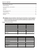
TABLE OF CONTENTS Important Safety Information ............................................................................................................4 Product Features............................................................................................................................... 6 Air For Combustion and Ventilation................................................................................................... 8 Installation.............................................................
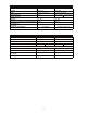
SERIES IR6NTDG-1/NMDG-1 IR12NTDG-1/NMDG-1 MAX BTU 6,000 12,000 Fuel Type Natural Gas Natural Gas Ignition Electronic Push Button Electronic Push Button Manifold Pressure 5 in. W.C. 5" W.C. (IR12NTDG-1) 4" W.C. (IR12NMDG-1) 14 in. W.C. 14 in. W.C. Inlet Gas Pressure Maximum *Minimum (*For purposes of input adjustment) 6 in. W.C. Dimensions (in.) ( H x W x D) 20.00 in. x 17.32 in. x 9.49 in. 20.00 in. x 17.32 in. x 9.49 in. Not Available 120V/60Hz,18W, 0.
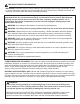
IMPORTANT SAFETY INFORMATION IMPORTANT: Read this owner’s manual carefully and completely before trying to assemble, operate, or service this heater. Improper use of this heater can cause serious injury or death from burns, fire, explosion, electrical shock, and carbon monoxide poisoning. Installation and repair should be done by a qualified service person. The appliance should be inspected before use and at least annually by a professional service person.
SAFETY INFORMATION WARNING: Do not use any accessories not approved for use with this heater. CALIFORNIA PROPOSITION 65 Fuels used in gas or oil fired appliances and the products of combustion of such fuels contain chemicals known to the state of California to cause cancer, birth defects or other reproductive harm. This product contains chemicals, including lead and lead compounds, known to the state of California to cause cancer, birth defects or other reproductive harm. Wash hands after handling. 1.
PRODUCT FEATURES SAFETY PILOT This heater has a pilot with an Oxygen Depletion Sensing (ODS) safety shutoff system. The ODS/pilot shuts off the heater if there is not enough fresh air and cuts off main burner gas in the event of flame out. LEG KIT(Select models) 2 support legs and 4 support leg screws are included for floor mounting the heater. See page 13. NOTE: This is an optional accessory and is not required for operation of the heater.
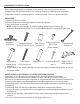
PREPARING FOR INSTALLATION Before beginning assembly or operation of the product, make sure all parts are present. Compare parts with package contents list. If any part is missing or damaged, do not attempt to assemble, install or operate the product. Contact customer service for replacement parts. UNPACKING 1. Remove heater from carton. 2. Remove all protective packaging applied to heater for shipping 3. Verify all contents are present. NOTE: Support Leg Screw (M4*15) (Select Models), Wood Screw (ST4.
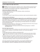
PREPARING FOR INSTALLATION AIR FOR COMBUSTION AND VENTILATION CAUTION: This heater shall not be installed in a room or space unless the required volume of indoor combustion air is provided by the method described in the National Fuel Gas Code, ANSI Z223.1/NFPA54, the International Fuel Gas Code, or applicable local codes. PRODUCING ADEQUATE VENTILATION All spaces in homes fall into one of the three following ventilation classifications: 1. Unusually Tight Construction 2. Unconfined Space 3.
PREPARING FOR INSTALLATION DETERMINING FRESH-AIR FLOW FOR HEATER LOCATION Determining if You Have a Confined or Unconfined Space Use this worksheet to determine if you have a confined or unconfined space. Space: Includes the room in which you will install heater plus any adjoining rooms with doorless passageways or ventilation grills between the rooms. 1. Determine the volume of the space Length × Width × Height = cu. ft. (volume of space) Example: Space size 20 ft. (length) × 16 ft.(width) × 8 ft.
PREPARING FOR INSTALLATION Ventilation Air From Inside Building This fresh air would come from adjoining unconfined space. When ventilating to an adjoining unconfined space, you must provide two permanent openings: one within 12 in. of the wall connecting the two spaces (see options 1 and 2, Fig. 1). You can also remove door into adjoining room (see option 3, Fig. 1). Follow the National Fuel Gas Code NFPA 54/ANS Z223.1. Air for Combustion and Ventilation for required size of ventilation grills or ducts.
INSTALLATION NOTICE: This heater is intended for use as supplemental heat. Use this heater along with your primary heating system. Do not install this heater as your primary heat source. WARNING: A qualified technician must install heater. Follow all local codes. WARNING: Maintain the minimum clearances. If possible, provide greater clearances from the floor, ceiling, and adjoining wall than required. CAUTION: This heater creates warm air currents. These currents move heat to wall surfaces next to heater.
INSTALLATION INSTALLING IGNITOR BATTERY • Battery is included. • Unscrew ignitor cap and insert included battery negative (flat) side down (See Fig. 7). Replace Ignitor cap. • Be sure to observe proper polarity (+/-) when installing or replacing the battery. Damage due to improper battery installation may void the warranty on the product. • Install/replace the battery according to the type and quantity stated in table below. • Remove battery when depleted.
INSTALLATION Fig. 12- Fan Wiring Diagram Fig. 11 - Operating Fan Fan Switch MAN Thermo-switch MAN 110/115 VAC AUTO Fan Rocker Switch AUTO Black White Green LOCATING HEATER This heater is designed to be mounted on a wall or on a floor, using the Support Legs (Select Models) included with select models. For convenience and efficiency, install heater: 1. Where there is easy access for operation, inspection, and service. 2. In the coldest part of room. 3.
INSTALLATION Methods For Attaching Mounting Bracket To Wall Use only the last hole on each end of mounting bracket to attach bracket to wall. Attach mounting bracket to a wall only in one of two ways: 1. Attaching to wall stud: This method provides the strongest hold. Insert wood screws (ST.8*45-16) through mounting bracket and into wall studs. 2.
INSTALLATION Attaching to Expansion Bracket Method For attaching mounting bracket to hollow walls (wall areas between studs) or solid walls (concrete or masonry): Fig. 17 - Folding the Expansion Bracket 1. Drill holes at marked locations using 5/16-inch drill bit. For solid walls (concrete or masonry), drill at least 1 inch deep. 2. Fold wall expansion bracket as shown in (See Fig. 17). 3. Insert wall expansion bracket (wings first) into hole. Tap expansion bracket flush to wall. Fig.
INSTALLATION CONNECTING TO GAS SUPPLY WARNING: A qualified service technician must connect heater to gas supply. Follow all local codes. IMPORTANT: This appliance requires a 3/8-inch NPT (National Pipe Thread) inlet connection to the pressure regulator. Never connect the heater to private (non-utility) gas wells, commonly known as wellhead gas. WARNING: Do not overtighten gas connections. CAUTION: Use only new, black iron or steel pipe. Internally tinned copper tubing may be used in certain areas.
INSTALLATION Fig. 20 - Gas Connection Install sediment trap in supply line as shown (See Fig. 20). Place sediment trap where it is within reach for cleaning. Place sediment trap where trapped matter is not likely to freeze. A sediment trap traps moisture and contaminants. This keeps them from going into heater controls. If sediment trap is not installed or is installed wrong, heater may not run properly.
OPERATION FOR YOUR SAFETY READ BEFORE LIGHTING WARNING: If you do not follow these instructions exactly, a fire or explosion may result causing property damage, personal injury or loss of life. A. This appliance has a pilot which must be lighted using the Ignitor. When lighting the pilot, follow these instructions exactly. B. BEFORE LIGHTING smell all around the appliance area for gas. Be sure to smell next to the floor because some gas is heavier than air and will settle on the floor.
OPERATION LIGHTING INSTRUCTIONS If the control knob does not pop up when released, stop and immediately and call your service technician or gas supplier. 8. Turn on all electric power to the appliance. 9. Turn control knob counter clockwise to desired setting. Burner Patterns (Manual Control) HIGH LOW LOW LOW OFF HIGH MED MED OFF HIGH HIGH OFF 1 4 5 Fig. 22b 1 4 5 FF 3 PILOT 2 O Note: If pilot goes out repeat steps 3 through 7. Wait (1) minute before attempting to light pilot again.
OPERATION LIGHTING INSTRUCTIONS OT 1 4 5 ON 5 1 3 4 2 OFF 2 3 O FF OFF P IL Burner Patterns (Thermostatic Control) PILOT TO TURN OFF GAS TO APPLIANCE 1. Turn off all electric power to the appliance if service is to be performed. 2. Push in gas control knob slightly and turn clockwise to "OFF" or " DO NOT FORCE. 2 3 4 5 OFF P IL OT 2 3 Manual 1 4 5 OFF P IL 1 The thermostat used on this heater senses the room temperature. At times the room may exceed the set temperature.
OPERATION INSPECTING BURNERS Check pilot flame pattern daily when in use and at least yearly by a qualified service agency. PILOT FLAME PATTERN Fig. 26 shows a correct pilot flame pattern. Fig. 27 shows an incorrect pilot flame pattern. The incorrect pilot flame is not touching the thermocouple. This will cause the thermocouple to cool, which shuts the heater off. If pilot flame pattern is incorrect: • turn heater off (see “To Turn Off Gas to Appliance” on page 19) • see Troubleshooting pages 23 through 26.
CARE AND MAINTENANCE Fig. 30 - Front Panel Removal NOTE: Before servicing you will need to remove the front panel of the heater. There are 4 Philips head screws, 2 on the left side and 2 on the right, securing the front panel to the heater (See Fig. 30). Always allow the unit to cool for at least thirty minutes before attempting to remove the front panel. WARNING: Turn off heater, unplug electrical cord and let cool before servicing.
TROUBLESHOOTING WARNING: If you smell gas: • Shut off gas supply. • Do not try to light any appliance. • Do not touch any electrical switch; do not use any phone in your building. • Immediately call your gas supplier from a neighbor’s phone. Follow the gas supplier’s instructions. • If you cannot reach your gas supplier, call the fire department. IMPORTANT: Operating heater where impurities in air exist may create odors.
TROUBLESHOOTING PROBLEM POSSIBLE CAUSE CORRECTIVE ACTION 1. Control knob is not fully ODS/pilot lights pressed in. but flame goes out when control knob is 2. Control knob is not pressed in long enough. released. 3. Equipment shutoff valve is not fully open. 4. Thermocouple connection is loose. 5. Thermocouple damaged. 6. Control valve damaged. 7. Inlet gas pressure is too high 1. Press in control knob fully. Burner(s) does not light afterODS/pilot is lit. 1. Thermostat setting too low. 2.
TROUBLESHOOTING PROBLEM POSSIBLE CAUSE CORRECTIVE ACTION White powder residue forming within burner box or on adjacent walls or furniture. 1. When heated, the vapors from furniture polish, wax, carpet cleaners, etc., turn into white powder residue. 1. Turn heater off when using furniture polish, wax, carpet cleaner or similar products. Heater produces unwanted odors. 1. Heater is burning vapors from paint, hair spray, glues, etc. See IMPORTANT statement, page 22. 2. Gas leak.
TROUBLESHOOTING PROBLEM POSSIBLE CAUSE CORRECTIVE ACTION Fan is not spinning. (Select models) 1. There is no power to the fan. 1. Verify fan is plugged in and set to "MAN" or "AUTO". 2. Allow 5-10 minutes for fan to engage. 3. Replace fan. 2. Fan is set to "AUTO". 3. Fan motor is bad. Fan is making a loud noise. (Select models) 1. Fan housing or blades are dirty. 2. Fan rotation is blocked. 3. Defective fan. 26 1. See "Cleaning Fan", page 22. 2. Verify wiring is not in fan path. 3. Replace fan.
REPLACEMENT PARTS LIST For replacement parts, call our customer service department at 1-877-447-4768, 8:30 a.m. –4:30 p.m., CST, Monday – Friday. WARNING: Only use genuine replacement parts from the GHP Group, Inc. Using any parts other than the original replacement parts may result in property damage, personal injury or even death. 10 4 9 8 5 2 14 3 6 1 7 ITEM No. DESCRIPTION QTY PART NO.
WARRANTY 1. not be covered by this warranty, nor shall the LIMITED WARRANTY: The manufacturer warrants that your new product is free This limited warranty is extended to the original retail purchaser of this Forced Air/Convection/Radiant Heater and warrants againstfor any same. manufacturer assume responsibility from manufacturing and material defects for a period of defect in materials and workmanship for a period of one (1) year from the date of retail sale. GHP Group, Inc.
WARRANTY REGISTRATION IMPORTANT: We urge you to fill out your warranty registration card within fourteen (14) days of date of purchase. You can also register your warranty on the internet at www.ghpgroupinc.com. Complete the entire serial number. Retain this portion of the card for your records. GHP Group, Inc. 6440 W Howard GHP Group, Inc. St Niles, IL 60714-3302 GHP 8280 Austin Ave. Morton Grove, IL 60053-3207 Tel: (877) 447-4768 www.ghpgroupinc.com Tel: (877) 447-4768 www.ghpgroupinc.