INDOOR/OUTDOOR PRODUCTS KEROSENE PORTABLE FORCED AIR HEATERS “USER’S MANUAL AND OPERATING INSTRUCTIONS” COMPLIES WITH ANSI A10.10-1998 CAN/CSA/B140.0-03 AND CSA B140.8-1967 MODEL : KFA400DGD Before the first use of this heater, please read this USER’S MANUAL very carefully. This USER’S MANUAL has been designed to instruct you as to the proper manner in which to assemble, maintain, store, and most importantly, how to operate the heater in a safe and efficient manner.
NEVER LEAVE THE HEATER UNATTENDED WHILE BURNING! DANGER: IMPROPER USE OF THIS HEATER CAN RESULT IN SERIOUS INJURY OR DEATH FROM BURNS, FIRE, EXPLOSION, ELECTRICAL SHOCK AND/OR CARBON MONOXIDE POISONING. WARNINGS: 1. RISK OF INDOOR AIR POLLUTION! • Use this heater only in well ventilated areas. Provide at least a three-square foot (2,800 sq. cm.) opening of fresh outside air for each 100,000 BTU/hr. of heater rating. • People with breathing problems should consult a physician before using the heater.
NEVER LEAVE THE HEATER UNATTENDED WHILE BURNING! CONTENTS OF USER’S MANUAL ITEM PAGE # PRECAUTIONS - SAFETY GUIDE 1. INTRODUCTION 2. FEATURES 3. UNPACKING AND ASSEMBLY 4. KEROSENE (1-K OR NO. 1 FUEL OIL) 5. OVERVIEW OF HEATER DESIGN 6. FUELING YOUR HEATER 7. OPERATION 8. LONG TERM STORAGE OF YOUR HEATER 9. MAINTENANCE 10 REPLACING FUSE 11 TROUBLE SHOOTING GUIDE 12 WIRING DIAGRAM 13 SPECIFICATIONS 14 EXPLODED PARTS DRAWING 15 PARTS LIST 1 2 2 3 4 5 5 6 8 9 14 15 16 17 18 19 1.
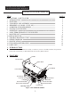
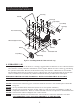
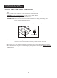
NEVER LEAVE THE HEATER UNATTENDED WHILE BURNING! 3. UNPACKING AND ASSEMBLY 1. REMOVE THE HEATER AND ALL PACKING MATERIALS FROM THE BOX. (See Fig.2) NOTE: Save the shipping carton and packing materials for future storage. Wheels Screw(L) Cord Wrap Cap Nuts(L) Screw(S) Bushings Washers Nuts Cap Nuts(S) Hardware Kit Part No : HW-KFA1019 Handle Handle Wheel Support Frame Threaded Axle Figure 2. PACKING MATERIALS 2.
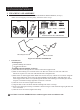
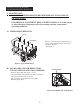
NEVER LEAVE THE HEATER UNATTENDED WHILE BURNING! Screw(L) Handle Screw(S) Cap Nut(S) Cord Wrap Screw(S) Fuel Tank Flange Wheel Support Frame Wheel Air Inlet Nut Washer Threaded Axle Cap Nut(L) Bushing Figure 3. Assembling Handle & Wheel and Cord wrap 4. KEROSENE (1-K) For optimal performance of this heater, it is strongly suggested that 1-K kerosene be used. 1-K kerosene has been refined to virtually eliminate contaminants, such as sulpher.
NEVER LEAVE THE HEATER UNATTENDED WHILE BURNING! 5. OVERVIEW OF HEATERS DESIGN Fuel System: This heater is equipped with a Fuel pump(Gear)that pulls fuel through the fuel line connected to the fuel tank and then pushes fuel through a filter and a solenoid valve and out the burner head nozzle. This fuel is sprayed into the combustion chamber in a fine mist. “Sure Fire Ignition”: The electronic ignitor sends voltage to a specially designed spark plug. The spark plug ignites the fuel and air mixture.
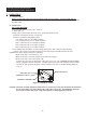
NEVER LEAVE THE HEATER UNATTENDED WHILE BURNING! 7. OPERATION A.) VENTILATION RISK OF INDOOR AIR POLLUTION/USE HEATER ONLY IN WELL VENTILATED AREAS. Provide at least a three-square foot(2,800 sq. cm.) opening of fresh outside air for each 100,000 BTU/hr. of heater rating. B.) OPERATION TO START HEATER 1. Fill fuel tank with kerosene or No. 1 fuel oil. 2. Attach fuel cap. 3. Plug power cord of heater into three-prong, grounded extension cord. Extension cord must be at least six feet long.
NEVER LEAVE THE HEATER UNATTENDED WHILE BURNING! TO STOP HEATER CAUTION ; Never unplug heater while heater is running Heater must go through cooling cycle. The cooling cycle cools the combustion chamber. Damage to heater can occur if combustion chamber is not cooled. Do not restart heater until cooling cycle is complete. 1. Turn operating switch to “OFF”. This will cause heater flame to go out. The motor will continue to run during the cooling cycle. (Room Temp.
NEVER LEAVE THE HEATER UNATTENDED WHILE BURNING! 8. LONG TERM STORAGE OF YOUR HEATER 1. Remove fuel drain bolt from rear bottom side of fuel tank using 3/4” socket or adjustable wrench and drain. 2. Using a small amount of kerosene, swirl and rinse the inside of the tank. NEVER mix water with the kerosene as it will cause rust inside the tank. Pour the kerosene out making sure that you remove it all. IMPORTANT : Do not store kerosene over summer months for use during next heating season.
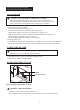
NEVER LEAVE THE HEATER UNATTENDED WHILE BURNING! 9. MAINTENANCE WARNING!! NEVER SERVICE HEATER WHILE IT IS PLUGGED IN OR WHILE HOT! USE ORIGINAL EQUIPMENT REPLACEMENT PARTS. Use of third party or other alternate components will void warranty and may cause unsafe operating conditions. A.) UPPER SHELL REMOVAL Screw Shell Upper -Remove screws along each side and top of heater using medium phillips screw driver. -Lift upper shell off. (See Figure 7) Figure 7. Upper Shell Removal B.
NEVER LEAVE THE HEATER UNATTENDED WHILE BURNING! C.) SPARK PLUG SPARK PLUG CLEAN AND REGAP EVERY 600 HOURS OPERATION OR REPLACE AS NEEDED. - Remove upper shell (See page 9). - Remove spark plug wire from spark plug (See Figure 9) - Remove spark plug from burner head using medium phillips screw driver. - Clean and regap spark plug electrodes to 0.14”(3.5mm) gap. - Reinstall spark plug in burner head. - Attach spark plug wire to spark plug. - Reinstall upper shell. BURNER HEAD GAP SPARK PLUG WIRE D.
NEVER LEAVE THE HEATER UNATTENDED WHILE BURNING! E.) PHOTOCELL CLEAN PHOTO CELL ANNUALLY OR AS NEEDED. - Remove upper shell(See Page 9) - Remove photocell from photocell Bracket and disconnect photocell from connector. - Clean photocell lens with cotton swab. - Inspect photcell lens for damage. If damaged, replace photocell. PHOTOCELL BRACKET PHOTOCELL CONNECTOR INSTALL PHOTOCELL PHOTOCELL LENS 1)INCORRECT 2)CORRECT Figure 11. Clean photocell Lens F.
NEVER LEAVE THE HEATER UNATTENDED WHILE BURNING! G.) FUEL FILTER CLEAN TWICE PER HEATING SEASON OR AS NEEDED. Tank Fuel Filter - Remove fan guard (See Figure 11). SCREW PUMP - Disconnect fuel line (B) from pumpand pump fuel filter assembly with3/8” wrench (See Figure 14). - Remove two screws that fix bracket-filter to shell lower and remove bracket-filter. - Carefully pry fuel filter loose from fueltank with flat end of screwdriver.
NEVER LEAVE THE HEATER UNATTENDED WHILE BURNING! H.) PUMP PRESSURE ADJUSTIMENT - Remove pressure gauge plug from pump with 1/8” allen wrench. - Install accessory pressure gauge to pressure gauge port. (See Figure 16) - Start heater (See operation, page 6) Allow motor to reach full speed. - Adjust pressure. (Using a small flat blade screw driver) Turn pressure adj. Screw to clock wise to increase pressure. Turn screw to counter clock wise to decrease pressure. Set pump pressure to 125 PSI.
NEVER LEAVE THE HEATER UNATTENDED WHILE BURNING! 10. REPLACING FUSE NOTICE : This heater is fuse protected. If your heater fails to ignite, DO NOT RETURN YOUR HEATER TO THE STORE. Please follow the simple instruction below to inspect and change the fuse. PROCEDURE FOR REPLACING FUSE WARNING : SHOCK HAZARD To prevent personal injury, unplug the power cord before replacing fuse. 1. Unplug heater. 2. Turn Fuse Cover COUNTERCLOCKWISE 45° using a flat blade screwdriver and remove Fuse from Fuse Holder. 3.
NEVER LEAVE THE HEATER UNATTENDED WHILE BURNING! 11. TROUBLE SHOOTING GUIDE TROUBLE POSSIBLE CAUSE CORRECTIVE ACTION Heater ignites but MAIN PCB assembly shuts heater off after a short period of time. (Indicator lamp is flickering and room temp. display indicates “E1”) 1. 2. 3. 4. 5. Wrong pump pressure Dirty Fuel Filter Dirt in Nozzle Dirty Photocell Lens Photocell Assembly not properly installed. (Not seeing the flame) 6. Bad electrical connection between photocell and MAIN PCB assembly 7.
NEVER LEAVE THE HEATER UNATTENDED WHILE BURNING! WIRING DIAGRAM CONTROL PCB BLACK CN7 POWER LAMP (LED) WHITE CN4 THERMOSTAT (TEMP. CONTROL) RED CN3 LIMIT CONTROL BLACK SOL.
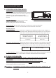
NEVER LEAVE THE HEATER UNATTENDED WHILE BURNING! 13. SPECIFICATIONS 32.8" 52.5" 31.4" KFA400DGD MODEL BTU/Hr Fuel Consumption-Gal./ ( ./Hr) Fuel Tank Capacity-Gal ( ) Pump Pressure PSI (kgf/ ) Volts/Hz/Amps Phase Size(D W H), Inch( ) Weight Ibs. ( ) KFA400DGD 400,000 3.0(11.36) 29.0(110.0) 125(8.79) 120VAC/60/4.4 1 52.5” × 31.4” × 32.8” (1,334 × 798 × 834) 150(68.
NEVER LEAVE THE HEATER UNATTENDED WHILE BURNING! 14. EXPLODED PARTS DRAWING (KFA400DGD MODEL) NOTE: SPECIFY MODEL NUMBER AND PART NUMBER WHEN ORDERING PARTS.
NEVER LEAVE THE HEATER UNATTENDED WHILE BURNING! 15. PARTS LIST KEY No.
NEVER LEAVE THE HEATER UNATTENDED WHILE BURNING! 15. PARTS LIST (BURNER HEAD ASSEMBLY & MOTOR AND PUMP ASSEMBLY) NOTE: SPECIFY MODEL NUMBER AND PART NUMBER WHEN DRDERING PARTS. KEY NO. 1 2 3 4 5 6 7 8 9 10 KEY NO.
NEVER LEAVE THE HEATER UNATTENDED WHILE BURNING! 15. PARTS LIST (Wheel and Handle) NOTE: SPECIFY MODEL NUMBER AND PART NUMBER WHEN ORDERING PARTS. KEY NO. 1 2 3 4 5 6 6-1 6-2 6-3 DESCRIPTION 3551-0036-00 2 3551-0098-00 Cord Wrap 3221-0052-00 Handle Threaded Axle 1 2 3541-0096-00 Wheel 1 3720-0004-00 2 Screw (L) INCLUDED IN HARDWARE KIT 6 Nut INCLUDED IN HARDWARE KIT 8 Hardware Kit Screw (S) Cap Nut(S) 6-6 Flat Washer 6-7 QTY Wheel Support Frame 6-4 6-5 PART NO.