INDOOR/OUTDOOR PRODUCTS KEROSENE PORTABLE FORCED AIR HEATERS “USER’S MANUAL AND OPERATING INSTRUCTIONS” COMPLIES WITH UL733 AND ANSI A10.10-1990 CAN/CSA/B140.0-03 AND CSA B140.8-1967 MODEL : RMC-KFA45DGD, RMC-KFA75TDGD, RMC-KFA125TDGD RMC-KFA170TDGD, RMC-KFA210TDGD, RMC-KFA210TDGD-01 Before the first use of this heater, please read this USER’S MANUAL very carefully.
NEVER LEAVE THE HEATER UNATTENDED WHILE BURNING! DANGER: IMPROPER USE OF THIS HEATER CAN RESULT IN SERIOUS INJURY OR DEATH FROM BURNS, FIRE, EXPLOSION, ELECTRICAL SHOCK AND/OR CARBON MONOXIDE POISONING. WARNINGS: 1. RISK OF INDOOR AIR POLLUTION! • Use this heater only in well ventilated areas. Provide at least a three-square foot (2,800 sq. cm.) opening of fresh outside air for each 100,000 BTU/hr. of heater rating. • People with breathing problems should consult a physician before using the heater.
NEVER LEAVE THE HEATER UNATTENDED WHILE BURNING! CONTENTS OF USER’S MANUAL ITEM PAGE # PRECAUTIONS - SAFETY GUIDE 1. INTRODUCTION 2. FEATURES 3. UNPACKING AND ASSEMBLY 4. KEROSENE (1-K OR NO. 1 FUEL OIL) 5. OVERVIEW OF HEATER DESIGN 6. FUELING YOUR HEATER 7. OPERATION 8. LONG TERM STORAGE OF YOUR HEATER 9. MAINTENANCE 10. REPLACING FUSE 11. TROUBLE SHOOTING GUIDE 12. WIRING DIAGRAM 13. SPECIFICATIONS 14. EXPLODED PARTS DRAWING 15. PARTS LIST 1 2 2 4 7 8 9 9 10 11 15 16 17 18 19 21 1.
NEVER LEAVE THE HEATER UNATTENDED WHILE BURNING! Front Handle Upper Shell Hot Air Outlet Shell Lower Fuel Gauge Fuel Cap Side Cover Lamp Thermostot Knob Fan Guard Power Cord Power/Reset Switch Pneumatic Wheel Drain Plug Figure 2.
NEVER LEAVE THE HEATER UNATTENDED WHILE BURNING! 3. UNPACKING AND ASSEMBLY 1. REMOVE THE HEATER AND ALL PACKING MATERIALS FROM THE BOX. (Fig. 4 and 5) NOTE : Save the shipping carton and packing materials for future storage.
NEVER LEAVE THE HEATER UNATTENDED WHILE BURNING! 2. ASSEMBLY A. For RMC-KFA45DGD/75TDGD Models only Tools Required • Medium Phillips Screwdriver. Assembling Handle 1. Lift front guard for arrow direction and make sure that guard’s wedged portion fits into the slit hole on the upper housing. 2. Align the holes in the upper housing with ttwo mounting holes on the handle as shown in Figure 6. 3. Secure handel with Screws with provided. Handle Screw Frong Guard Wedged Portion Slit Hole B.
NEVER LEAVE THE HEATER UNATTENDED WHILE BURNING! C. For RMC-KFA170/210TDGD/210TDGD-01 Models only Tools Required • Medium Phillips Screwdriver. • M5 open, or adjustable wrench • Long nose pliers. 1. Slide axle through wheel support frame. Install wheel bushings and wheels on axle. NOTE : When installing wheels, tube valve should face out from support frame (Figure 8). 2. Place flat washers and cotter pin on axle ends and bend cotter pins with long nose pliers to secure. 3.
NEVER LEAVE THE HEATER UNATTENDED WHILE BURNING! D. For RMC-KFA210DGP-01 Model Only. Assembling BTU Control Valve Knob direction when install valve to End Filter Cover. 1. Align slit hole on body of Valve with Tab on the End Filter Cover as shown in Figure 9. 2. Insert hooked leg of valve fully into slot of End Filter Cover so that hooked leg is completely locked to Slot.
NEVER LEAVE THE HEATER UNATTENDED WHILE BURNING! 5. OVERVIEW OF HEATERS DESIGN Fuel System : This heater is equipped with an electric air pump that forces air through the air line connected to the fuel intake and then through a nozzle in the burner head. When the air passes in front of the fuel intake it causes fuel to rise from the tank and into the burner nozzle. This fuel and air mixture is then sprayed into the combustion chamber in a fine mist.
NEVER LEAVE THE HEATER UNATTENDED WHILE BURNING! 6. FUELING YOUR HEATER NEVER FILL THE HEATER FUEL TANK IN THE LIVING SPACE : FILL THE TANK OUTDOORS. DO NOT OVERFILL YOUR HEATER AND BE SURE HEATER IS LEVELED. IMPORTANT NOTICE REGARDING FIRST IGNITION OF HEATER : The first time you light the heater, it should be done outdoors. This allows the oils, etc. used in manufacturing the heater to burn off outside. WARNING!! : NEVER REFILL HEATER FUEL TANK WHEN HEATER IS OPERATING OR STILL HOT. 7. OPERATION A.
NEVER LEAVE THE HEATER UNATTENDED WHILE BURNING! NOTICE : The major electrical components of this heater are protected by a safety fuse mounted to the PCB board. If your heater fails to start, check this fuse first and replace as necessary. You should also check your power source to insure that proper voltage and frequency are being supplied to the heater. TO STOP HEATER 1. Turn switch to “OFF” and unplug power cord. TO RESTART HEATER 1.Wait 10 seconds after stopping heater. 2.
NEVER LEAVE THE HEATER UNATTENDED WHILE BURNING! 9. MAINTENANCE WARNING!! : NEVER SERVICE HEATER WHILE IT IS PLUGGED IN OR WHILE HOT! USE ORIGINAL EQUIPMENT REPLACEMENT PARTS. Use of third party or other alternate components will void warranty and may cause unsafe operating conditions. A.) FUEL TANK Screw Upper Shell FLUSH EVERY 200 HOURS OF OPERATION OR AS NEEDED (SEE STORAGE, PAGE 9) Air Intake Filter B.) AIR INTAKE FILTER WASH AND DRY WITH SOAP AND WATER EVERY 500 HOURS OF OPERATION OR AS NEEDED.
NEVER LEAVE THE HEATER UNATTENDED WHILE BURNING! E.) NOZZLE REMOVE DIRT IN NOZZLE AS NEEDED (SEE PAGE 16). (For RMC-KFA45DGD/75/125/170TDGD Models Only) - Remove upper shell (See page 10). - Remove fan blade (See page 10). - Remove fuel and air line hoses from burner head. - Remove ignitor wire from spark plug. - Remove three screws using medium phillips screwdriver and remove burner head from combustion chamber. - Remove spark plug from burner head using medium phillips screwdriver.
NEVER LEAVE THE HEATER UNATTENDED WHILE BURNING! Spark Plug F.) SPARK PLUG Ignitor wire Burner Head Spark Plug GAP CLEAN AND REGAP EVERY 600 HOURS OPERATION OR REPLACE AS NEEDED. (For RMC-KFA45DGD/75/125/170TDGD Models Only) - Remove upper shell (See page 10). - Remove fan (See page 10). - Remove ignitor wire from spark plug. - Remove spark plug from burner head using medium phillips screwdriver. - Clean and regap spark plug electrodes to 3.5mm gap. - Reinstall spark plug in burner head.
NEVER LEAVE THE HEATER UNATTENDED WHILE BURNING! H.) FUEL FILTER CLEAN OR REPLACE TWICE A HEATING SEASON OR AS NEED. - Remove side cover screws using medium phillips screwdriver. - Disconnect switch wires from power switch and remove side cover. - Pull fuel line off fuel filter neck. - Turn fuel filter 90˚ to counter clockwise and pull to remove (RMC-KFA45DGD/75TDGD Models only). - Turn fuel filter 90˚ to clockwise and pull to remove (RMC-KFA125/170/210TDGD/210TDGD-01 Models only).
NEVER LEAVE THE HEATER UNATTENDED WHILE BURNING! 10. REPLACING FUSE NOTICE : This heater is fuse protected. If your heater fails to ignite, DO NOT RETURN YOUR HEATER TO THE STORE. Please follow the simple instruction below to inspect and change the fuse. PROCEDURE FOR REPLACING FUSE WARNING : SHOCK HAZARD To prevent personal injury, unplug the power cord before replacing fuse. 1. Unplug heater. 2. Remove side cover screws using medium phillips screw driver. 3. Disconnect switch wires from power switch. 4.
NEVER LEAVE THE HEATER UNATTENDED WHILE BURNING! 11. TROUBLE SHOOTING GUIDE TROUBLE Heater ignites but MAIN PCB assembly shuts heater off after a short period of time. (Indicator Lamp is flickering and room temp. display indicates " E1 ") Heater will not ignite but motor runs for a short period of time.(Indicator Lamp is flickering and room temp.display indicates " E1 ") POSSIBLE CAUSE 1. Wrong pump pressure 2. Dirty Air Output,Air Intake or Lint Filter. 3. Dirty Fuel Filter. 4. Dirt in Nozzle. 5.
NEVER LEAVE THE HEATER UNATTENDED WHILE BURNING! 12.
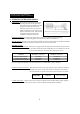
NEVER LEAVE THE HEATER UNATTENDED WHILE BURNING! 13. SPECIFICATIONS RMC-KFA45DGD/75TDGD Models 125TDGD 170/210TDGD D 36.0"(914 ) 43.5"(1105 ) W 19.0"(483 ) 23.9"(607 ) H 23.0"(584 ) 26.6"(675 ) RMC-KFA125/170/210TDGD/210TDGD-01 Models MODEL BTU/Hr Fuel Consumption - Gal./Hr(l./Hr) RMC-KFA45DGD RMC-KFA75TDGD RMC-KFA125TDGD RMC-KFA170TDGD RMC-KFA210TDGD RMC-KFA210TDGD-01 HIGH 45,000 75,000 125,000 170,000 210,000 210,000 LOW N/A N/A N/A N/A N/A 170,000 HIGH 0.35(1.32) 0.57(2.16) 0.
NEVER LEAVE THE HEATER UNATTENDED WHILE BURNING! 14. EXPLODED PARTS DRAWING (RMC-KFA45DGD/75/125/170TDGD Models Only) NOTE : SPECIFY MODEL NUMBER AND PART NUMBER WHEN ORDERING PARTS.
NEVER LEAVE THE HEATER UNATTENDED WHILE BURNING! 14. EXPLODED PARTS DRAWING (RMC-KFA 210TDGD/210TDGD-01 Models Only) NOTE : SPECIFY MODEL NUMBER AND PART NUMBER WHEN ORDERING PARTS.
NEVER LEAVE THE HEATER UNATTENDED WHILE BURNING! 15. PARTS LIST (RMC-KFA45DGD/75/125/170TDGD Models Only) KEY NO. DESCRIPTION 1 2 3 4 5 6 7 8 9 10 11 12 13 14 15 16 17 18 19 20 21 22 23 24 24-1 24-2 24-3 24-4 24-5 24-6 24-7 24-8 24-9 24-10 24-11 25 26 27 27-1 27-2 27-3 27-4 Fuel Tank Assmebly Drain-Plug Fuel Gauge Fuel Filter Assmbly Fuel Cap Cord Bushing Power Cord Thermistor Button Support Display P.C.
NEVER LEAVE THE HEATER UNATTENDED WHILE BURNING! 15. PARTS LIST (RMC-KFA45DGD/75/125/170TDGD Models Only) KEY NO.
NEVER LEAVE THE HEATER UNATTENDED WHILE BURNING! 15. PARTS LIST (RMC-KFA210TDGD/210TDGD-01 Models Only) KEY NO.
NEVER LEAVE THE HEATER UNATTENDED WHILE BURNING! 15. PARTS LIST (RMC-KFA210TDGD/210TDGD-01 Models Only) KEY NO.
NEVER LEAVE THE HEATER UNATTENDED WHILE BURNING! 15. PARTS LIST (WHEELS AND HANDLE) 1) RMC-KFA45DGD/75TDGD MODELS KEY NO. DESCRIPTION 1 2 Handle Hardware Kit PART NO. RMC-KFA45DGD/75TDGD 3231-0073-00 HW-KFA1000 2 1 Quantity 1 1 2) RMC-KFA125TDGD MODEL KEY NO. DESCRIPTION 1 2 3 4 5 5-1 5-2 5-3 5-4 5-5 5-6 Front Handle Wheel Support Frame Axle Wheel Hardware Kit Screw(S) Screw(L) Flange Screw Nut Cotter Pin Washer PART NO.
EDITION 2009 4221 - 0059- 00 04/09 Rev.