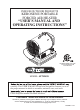
INDOOR/OUTDOOR PRODUCTS KEROSENE PORTABLE FORCED AIR HEATER “USER’S MANUAL AND OPERATING INSTRUCTIONS” COMPLIES WITH UL733 AND CAN/CSA/B140.0-03 AND CSA B140.8-1967 MODEL: SF70DGD carefully. This USER’S MANUAL has been designed to instruct you as to the proper manner in which to assemble, maintain, store, and most Please keep this manual for future reference. CONSUMER : Retain this manual for future reference.
NEVER LEAVE THE HEATER UNATTENDED WHILE BURNING! DANGER: IMPROPER USE OF THIS HEATER CAN RESULT IN SERIOUS INJURY OR DEATH FROM BURNS, FIRE, EXPLOSION, ELECTRICAL SHOCK AND/OR CARBON MONOXIDE POISONING. WARNINGS: 1. RISK OF INDOOR AIR POLLUTION! • Use this heater only in well ventilated areas. Provide at least a three-square foot (2,800 sq. cm.) opening of fresh outside air for each 100,000 BTU/hr. of heater rating. • People with breathing problems should consult a physician before using the heater.
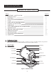
NEVER LEAVE THE HEATER UNATTENDED WHILE BURNING! CONTENTS OF USER’S MANUAL ITEM PAGE # PRECAUTIONS - SAFETY GUIDE 1. INTRODUCTION 2. FEATURES 3. UNPACKING AND ASSEMBLY 4. FUELS 5. OVERVIEW OF HEATER DESIGN 6. FUELING YOUR HEATER 7. OPERATION 8. LONG TERM STORAGE OF YOUR HEATER 9. MAINTENANCE 10. TROUBLE SHOOTING GUIDE 11. WIRING DIAGRAM 12. SPECIFICATIONS 13. EXPLODED PARTS DRAWING 14. PARTS LIST 1 2 2 3 3 4 4 5 6 6 10 11 11 12 13 1. INTRODUCTION Please read this USER’S MANUAL carefully.
NEVER LEAVE THE HEATER UNATTENDED WHILE BURNING! 3. UNPACKING AND ASSEMBLY 1. UNPACKING REMOVE THE HEATER AND ALL PACKING MATERIALS FROM THE BOX.( Fig. 2 ) NOTE : Save the shipping carton and packing materials for future storage. 2. ASSEMBLY Handle Heat Shield Figure 2. Packing Materials Tools Required • Medium Phillips Screw driver. Bolt Handle 1. Remove the pre-assembled Bolts on the shell Shell and shell ring. Remove Bolts 2.
NEVER LEAVE THE HEATER UNATTENDED WHILE BURNING! 5. OVERVIEW OF HEATERS DESIGN The Fuel System : This heater is equipped with a high-pressure electronic pump. The pump draws fuel up from the fuel tank to the nozzle in the burner head. It is sprayed into the combustion chamber in a fine mist where it is mixed with air for combustion. The Air System : A blower motor assembly forces air around the combustion chamber, where it is super-heated and forced out the front of the chamber.
NEVER LEAVE THE HEATER UNATTENDED WHILE BURNING! 7. OPERATION A.) VENTILATION RISK OF INDOOR AIR POLLUTION/USE HEATER ONLY IN WELL VENTILATED AREAS. Provide a fresh air opening of at least three square feet (2,800 sq. cm) for each 100,000 BTU/Hr. rating. Provide extra fresh air if more heaters are being used. Example : A SF70DGD heater requires one of the following: • a two-car garage door raised six inches (15.24 cm) • a single-car garage door raised nine inches (22.86 cm) • two, thirty-inch (76.
NEVER LEAVE THE HEATER UNATTENDED WHILE BURNING! CAUTION : Do not disconnect the power source or unplug the power cord until the cooling cycle has been completed! TO RESTART THE HEATER 1.Wait 10 seconds after cooling cycle has completed. 2. Turn the Operating Switch to "ON" position. 3. Be sure to follow all starting procedure precautions. CAUTION : DO NOT operate heater without heat shield assembled to the heater. Temperature of the floor is hot while in operation.
NEVER LEAVE THE HEATER UNATTENDED WHILE BURNING! Fuel Tank C) FUEL FILTER IN FUEL TANK Fuel Filter Clean twice per heating season or as needed 1) Pull Fule Line & Fuel Return Line off from Fuel Filter neck. 2) Turn Fuel Filter 90˚ to counter clockwise and pull to remove. 3) Wash Filter with clean kerosene and replace in tank. 4) Attach Fuel Line & Fule Return Line to Fuel Filter neck. Fuel Return Line Fuel Line Figure 4.
NEVER LEAVE THE HEATER UNATTENDED WHILE BURNING! F) NOZZLE Burner Body Fuel Pipe Remove dirt in Nozzle or replace as needed 1) Remove Back Cover.(See Page 6) 2) Remove Burner Full Assembly.(See Page 7) 3) Remove Fuel Pipe from Electronic Pump and Burner Body using 12mm wrench. 4) Remove Ignitor Wire from Spark Plug. 5) Remove 3 screws with medium phillips screwdriver and remove Burner Assembly from Burner Supporter.
NEVER LEAVE THE HEATER UNATTENDED WHILE BURNING! H) FUEL PIPE Tightening Fuel Pipe annually or as needed. 1) Remove Back Cover.(See Page 6) 2) Tighten Fuel Pipe at Electronic Pump and at Burner Body using 12mm wrench. 3) Inspect Fuel Line for damage. If damaged or cracked, Replace Fuel Line. Fuel Pipe Burner Body I) ELECTRONIC PUMP Electronic Pump Replace Electronic Pump if broke or damaged. 1) Remove Back Cover.(See Page 6) 2) Remove Burner Full Assembly.
NEVER LEAVE THE HEATER UNATTENDED WHILE BURNING! 10. TROUBLE SHOOTING GUIDE TROUBLE POSSIBLE CAUSE CORRECTIVE ACTION Heater ignites but Control PCB Assembly shuts heater off after a short period of time. (Indicater Lamp is flickering once per 3sec.) 1. Dirty Fuel Filter. 2. Dirt in Nozzle. 3. Dirty Photocell Lens. 4. Photocell not properly installed. (Not seeing the flame) 5. Bad electrical connection between Photocell and Control PCB Assembly. 6. Defective Photocell. 7. Defective Electronic Pump. 8.
NEVER LEAVE THE HEATER UNATTENDED WHILE BURNING! 11. WIRING DIAGRAM BLOWER FAN RPM SENSOR BLK RED YEL BHI LIMIT CONTROL (OVERHEAT THERMOSTAT) CN1 BHI BLUE CN7 RED E/P DISPLAY PCB CN12 WHITE (Dis 3P) POWER LAMP (LED) CN8 BLACK OPERATING SWITCH PHOTO CELL CN5 WHITE VIBRATION SWITCH CN9 WHITE C O NP TC RB O L IGNITOR SPARK PLUG CN4 WHITE I.G CN13 BLACK SOL.
NEVER LEAVE THE HEATER UNATTENDED WHILE BURNING! 13. EXPLODED PARTS DRAWING NOTE : SPECIFY MODEL NUMBER AND PART NUMBER WHEN ORDERING PARTS.
NEVER LEAVE THE HEATER UNATTENDED WHILE BURNING! 14. PARTS LIST KEY NO. 1 2 3 4 5 6 7 8 9 10 11 12 13 14 15 16 17 18 19 20 21 22 23 23-1 23-2 23-3 23-4 23-5 24 25 26 27 28 29 29-1 1-1 1-2 1-3 1-4 1-5 1-6 1-7 29-2 29-3 29-4 29-5 PART NO.
NEVER LEAVE THE HEATER UNATTENDED WHILE BURNING! 14. PARTS LIST KEY NO. 29-6 29-7 29-8 29-9 29-10 29-11 29-12 29-13 29-14 29-15 15-1 15-2 15-3 15-4 15-5 15-6 15-7 15-8 29-16 29-17 29-18 29-19 29-20 29-21 29-22 29-23 29-24 29-25 29-26 30 31 32 33 34 35 36 37 38 39 40 41 42 PART NO.
Warranty LIMITED WARRANTY: This limited warranty is extended to the original retail purchaser of this Forced Air/Convection/Radiant Heater and warrants against any defect in materials and workmanship for a period of one (1) year from the date of retail sale.GHP Group, Inc., at it’s option, will either provide replacement parts or replace or repair the unit, when properly returned to the retailer where purchased or one of our service centers as directed by GHP Group,Inc.
WARRANTY REGISTRATION days of date of purchase. You can also register your warranty on the internet at www.ghpgroupinc.com. Complete the entire serial number. Retain this portion of the card for your records. GHP Group, Inc. 6440 W Howard St Niles, IL 60714-3302 Tel: (877) 447-4768 www.ghpgroupinc.com SAVE THIS CARD! Place Postage Stamp Here GHP Group, Inc.
PRODUCTOS PARA INTERIORES/EXTERIORES CALEFACTORE DE AIRE FORZADO PORTÁTILES DE KEROSENE “MANUAL DEL USUARIO E INSTRUCCIONES DE FUNCIONAMIENTO” CUMPLE CON UL733 Y CAN/CSA/B140.0-03 Y CSA B140.8-1967 MODELO: SF70DGD Antes de utilizar por primera vez este calefactor, lea muy atentamente el MANUAL DEL USUARIO. Este MANUAL DEL USUARIO ha sido diseñado para enseñarle la forma correcta de ensamblar, mantener, guardar y, Conserve este manual para consultarlo cuando sea necesario.
NUNCA DEJE DESATENDIDO EL CALEFACTOR MIENTRAS ESTÁ ENCENDIDO. PELIGRO: EL USO INCORRECTO DE ESTE CALEFACTOR PUEDE OCASIONAR LESIONES GRAVES O LA MUERTE POR QUEMADURAS, INCENDIO, EXPLOSIÓN, DESCARGA ELÉCTRICA Y/O INTOXICACIÓN POR MONÓXIDO DE CARBONO. ADVERTENCIAS: 1. RIESGO DE CONTAMINACIÓN DEL AIRE EN INTERIORES • Utilice este calefactor solo en áreas bien ventiladas.
NUNCA DEJE DESATENDIDO EL CALEFACTOR MIENTRAS ESTÁ ENCENDIDO. CONTENIDO DEL MANUAL DEL USUARIO N.º DE PÁG. TEMA PRECAUCIONES - GUÍA DE SEGURIDAD 1. INTRODUCCIÓN 2. CARACTERÍSTICAS 3. DESEMBALAJE Y ENSAMBLAJE 4. COMBUSTIBLES 5. DESCRIPCIÓN GENERAL DEL DISEÑO DEL CALEFACTOR 6. CÓMO ALIMENTAR EL CALEFACTOR 7. FUNCIONAMIENTO 8. ALMACENAMIENTO A LARGO PLAZO DEL CALEFACTOR 9. MANTENIMIENTO 10. GUÍA PARA LA RESOLUCIÓN DE PROBLEMAS 11. DIAGRAMA DE CABLEADO 12. ESPECIFICACIONES 13.
NUNCA DEJE DESATENDIDO EL CALEFACTOR MIENTRAS ESTÁ ENCENDIDO. 3. DESEMBALAJE Y ENSAMBLAJE 1. DESEMBALAJE RETIRE EL CALEFACTOR Y TODOS LOS MATERIALES DE EMBALAJE DE LA CAJA.(Figura 2 ) NOTA: Guarde la caja de envío y los materiales de embalaje para almacenamiento futuro. Manija Pantalla térmica Figura 2. Materiales de embalaje 2. ENSAMBLAJE Herramientas requeridas • Destornillador Phillips de tamaño medio. 1. Quite los pernos ensamblados previamente en la carcasa y el anillo de la carcasa. 2.
NUNCA DEJE DESATENDIDO EL CALEFACTOR MIENTRAS ESTÁ ENCENDIDO. 5. DESCRIPCIÓN GENERAL DEL DISEÑO DEL CALEFACTOR Sistema de combustible: Este calefactor está equipado con una bomba electrónica de alta presión. La bomba extrae combustible del tanque de combustible en dirección ascendente hasta la boquilla del cabezal del quemador.
NUNCA DEJE DESATENDIDO EL CALEFACTOR MIENTRAS ESTÁ ENCENDIDO. 7. FUNCIONAMIENTO A.) VENTILACIÓN RIESGO DE CONTAMINACIÓN DEL AIRE EN INTERIORES/UTILICE EL CALEFACTOR SOLO EN ÁREAS BIEN VENTILADAS. Mantenga una abertura para que ingrese aire fresco de al menos tres pies cuadrados (2800 cm cuadrados) por cada 100 000 BTU/h según las condiciones nominales de funcionamiento del calefactor. Mantenga otras aberturas para que ingrese aire fresco adicional si se utilizan más calefactores.
NUNCA DEJE DESATENDIDO EL CALEFACTOR MIENTRAS ESTÁ ENCENDIDO. PRECAUCIÓN: No desconecte la fuente de alimentación ni desenchufe el cable de alimentación hasta que se haya completado el ciclo de enfriamiento. PARA VOLVER A ENCENDER EL CALEFACTOR 1. Espere 10 segundos después de que se haya completado el ciclo de enfriamiento. 2. Coloque el interruptor de funcionamiento en la posición “ON” (ENCENDIDO). 3. Asegúrese de tomar todas las precauciones del procedimiento de encendido.
NUNCA DEJE DESATENDIDO EL CALEFACTOR MIENTRAS ESTÁ ENCENDIDO. C.) FILTRO DE COMBUSTIBLE DEL TANQUE DE COMBUSTIBLE Limpie dos veces por temporada de uso o según sea necesario. 1) 2) la mano o un destornillador plano. 3) 4) Filtro de combustible Manguera de combustible Tanque de combustible combustible del tanque D.) RETIRO DEL CONJUNTO COMPLETO DEL QUEMADOR 1) Retire la cubierta trasera (consulte la página 6). 2) Desconecte los cables de la PCB como se muestra en la Figura 5.
NUNCA DEJE DESATENDIDO EL CALEFACTOR MIENTRAS ESTÁ ENCENDIDO. F.) BOQUILLA Cuerpo del quemador Quite la suciedad de la boquilla o reemplácela según sea necesario. 1) Retire la cubierta trasera (consulte la página 6). 2) Retire el conjunto completo del quemador (consulte la página 7). 3) Retire el conducto de combustible de la bomba electrónica y del cuerpo del quemador utilizando una llave de 12 mm. 4) Retire el cable del dispositivo de encendido de la bujía.
NUNCA DEJE DESATENDIDO EL CALEFACTOR MIENTRAS ESTÁ ENCENDIDO. H.) CONDUCTO DE COMBUSTIBLE Ajuste el conducto de combustible anualmente o según sea necesario. 1) Retire la cubierta trasera (consulte la página 6). 2) Ajuste el conducto de combustible de la bomba electrónica y del cuerpo del quemador utilizando una llave de 12 mm. 3) Si está dañada o agrietada, reemplácela. Conducto de combustible Cuerpo del quemador Bomba electrónica I.
NUNCA DEJE DESATENDIDO EL CALEFACTOR MIENTRAS ESTÁ ENCENDIDO. 10. GUÍA PARA LA RESOLUCIÓN DE PROBLEMAS PROBLEMA POSIBLE CAUSA ACCIÓN CORRECTIVA El calefactor se enciende pero el conjunto de la PCB de control apaga el calefactor después de un período breve. (La luz indicadora titila una vez cada 3 segundos). 1. Filtro de combustible sucio. 2. Suciedad en la boquilla. 3. Lente de la fotocélula sucia. 4. La fotocélula no está instalada correctamente. (No se ve la llama). 5.
NUNCA DEJE DESATENDIDO EL CALEFACTOR MIENTRAS ESTÁ ENCENDIDO. 11.
NUNCA DEJE DESATENDIDO EL CALEFACTOR MIENTRAS ESTÁ ENCENDIDO. 13. VISTA DESARROLLADA DE LAS PIEZAS NOTA: ESPECIFIQUE EL NÚMERO DE MODELO Y EL NÚMERO DE PIEZA CUANDO SOLICITA PIEZAS.
NUNCA DEJE DESATENDIDO EL CALEFACTOR MIENTRAS ESTÁ ENCENDIDO. 14. LISTA DE PIEZAS N.º DE PIEZA N.
NUNCA DEJE DESATENDIDO EL CALEFACTOR MIENTRAS ESTÁ ENCENDIDO. 14. LISTA DE PIEZAS N.º DE REFERENCIA 29-6 29-7 29-8 29-9 29-10 29-11 29-12 29-13 29-14 29-15 15-1 15-2 15-3 15-4 15-5 15-6 15-7 15-8 29-16 29-17 29-18 29-19 29-20 29-21 29-22 29-23 29-24 29-25 29-26 30 31 32 33 34 35 36 37 38 39 40 41 42 N.
GARANTÍA GARANTÍA LIMITADA: Esta garantla limitada es extendida al comprador original al detalle de este Calentador de Aire Forcade/ Convecci6n/ Radiante y garantiza contra culquier defecto en materiales y funcionamiento por un periodo de un (1) año desde la fecha de vents al detalle. GHP Group.Inc.
REGISTRO DE GRATANTÍA IMPORTANTE: Lo invitamos a completar nuestro formulario de registro de garantía dentro de los siguentes 14 días a la fecha de compta. Usted tembién puede registar su garantía en el internet en www.ghpgroupinc.com. Complete el número de serie. Conserve esta parte de la tarjeta como su comprobante. GHP Group, Inc. 6440 W Howard St Niles, IL 60714-3302 Tel: (877) 447-4768 www.ghpgroupinc.com ¡GUARDE ESTA TARJETA! Ponga una Estampa Postal Aquí GHP Group, Inc.
Florida Connecticut Colorado California Arizona Arkansas Alabama Alaska Cutler Repair Service & Sales Inc. Integrated Industrial Services, Inc. Tool & Equipment Service Solution, LLC. AAA Propane Sales & Rental, Inc. High Desert Outdoor Power Metro Gas Equipment Co. Miller Electric Motor Service Inc Pueblo West Rental Center Azar EMS Boyce Industries, Inc.
Illinois Idaho Iowa Georgia Andy's Tool Repair Ben's Rental & Sales Brockhouse Sales & Service Carter's Small Engine Repair Custom Labor Unlimited F.B. McAfoos & Co Farm & Fleet of Belvidere #11 Farm & Fleet of Bloomington #17 Farm & Fleet of Decatur #23 Farm & Fleet of Kankakee #21 Farm & Fleet of Loves Park #31 Hahn Tool Repair J & J Enterprises Rick´s Electric Inc Rossiter Electric Motor U-Rent, Inc. Beals Motor Rewind Blink Electric Motors, Inc.
Kentucky Kansas Indiana Adam's Repair Service Gillum's Sales & Repair, Inc Hedgepeth Supply Co Morris Electric & Repair Naab Electric, Inc. All-Pro Repair Service Eskew Enterprises, Inc. General Rental Center, Inc. Griffith Rentals & Sales Industrial Motor & Tool Industrial Tool Sales & Service, Inc. LaFayette Mower Repair Midway Rentals, Inc. New Paris Pro Hardware & Farm Store Nichols Supply R &C'S Small Enginge Repair S & J Small Engine Sarver's Angola Power Equipment Co.
Michigan Maine Maryland Massachusetts Louisiana A-1 Rental, Inc. All Parts Equipment and Accessories Bill's Repair and Sharpening Bob´s Service Shop L.L.C. Bush Hardware CMR(Copenhaver Machine & Tool Repair) Contractors Equipment & Supply Don's Tractor & Equipment Sales Joe's Lawn and Garden Lange & Leaman Electric Mac's Service Equipment Martin Electric Motor Sales & Service Master Service Center Mid-Michigan Reapir Service, Inc. Millmark Products, Inc. Roger Agotte Electric, Inc.
North Dakota North Carloina Montana Missouri Minnesota Burke Outdoor, Inc. Express Pump Repair General Motor Repair & Service, Inc. Handy Rental, Inc. Haywood Tractor & Implement Haywood Tractor Company, Inc. Hufhams Small Engines J & S Tool Repair JE Womble & Sons; Small Engine Shop Leonard Electric Motor Repair, Inc. Lexington Mower Service McLamb LP Gas & Supply Co. Moores Dairy Equipment, Inc.
New York Nevada New Mexico New Jersey Nebraska All In One Rentals Astronumatic, LTD. C.I. Horst Small Engine Repair Eldred Power Equipment & Auto Parts, Inc. Forestiere Power Tool & Equip. Co. G & R´s Repair Good Day Dist. Ltd. Greg's Tractor and Small Engine Repair Groton Cycle Center Kerber & Sons Loper's Equipment Corp. Moyer's Sales & Services P & C Repair Para-Deys Tools Ped´s Electric Service R & D Mower & Snowblower Sales & Service, Inc.
Pennsylvania Oklahoma Ohio Brady's Small Engine Repair Brown's Equipment & Supply Co. Brownsville Hardware Burkholder's Motor Repair All Seasons Small Engine Repair Enid Electric Motor Service, Inc. Equipment One Rental & Sales, Inc. Mike's Sales & Repair Smith´s Small Engine Tauber LLC Apple Farm Supply Inc Brian Frank's Electric, Inc. Cambridge Power Inc.
Tennessee South Dakota South Carolina Rhode Island Authorized Equipment Service D & J Small Engines Jerry's A to Z Inc. Macon Small Engines Manchester Small Engine Master Repair Services Red Barn Motor Sports & Power Equipment, Inc. Roger's Electric Motor Service Ed's Repair / Stout Enterprises Four Bridges Small Engines La Porte's Mullins Tool Rental Summerville Lawn Mower & Heater Colonial Fix-It Shop & Small Appliance Hospital, Inc. Charles J.
Wisconsin Washington Utah Texas American Power Equipment Inc. Appliance Repair Bennett's Electric Motor Service Craig's Small Engine Farm & Fleet of Baraboo #28 Farm & Fleet of Chippewa Falls #09 Farm & Fleet of Dodgeville, Inc. #02 Burke Power Equipment & Small Engine Repair CHS Equipment Repair Services Industrial Specialties, Inc. Tuco Industrial Products, Inc.
Wyoming West Virginia Keith´s Small Engine Repair L & P Equipment & Repair Biedler´s Electric Motor Repair, Inc. Genteck Repair, LLC. Mac's Garage Nitro Lawnmower & Chainsaw, LLC. Noel's Outdoor Power Equipment Farm & Fleet of Janesville, Inc. #03 Farm & Fleet of LaCrosse #27 Farm & Fleet of Madison, Inc. #22 Farm & Fleet of Monroe, Inc. #24 Farm & Fleet of Oak Creek #29 Farm & Fleet of Platteville, Inc. #07 Farm & Fleet of Rice Lake, Inc.