CMS3 CMS 600-3 COMPACT MIXING SYSTEM Owner‘s Manual | Bedienungsanleitung
CMS3 2
CMS3 CONTENTS INTRODUCTION . . . . . . . . . . . . . . . . . . . . . . . . . . . . . . . . Scope of Delivery, Unpacking and Inspection . . . Warranty . . . . . . . . . . . . . . . . . . . . . . . . . . . . . . . . Installation and Connections . . . . . . . . . . . . . . . . HF-Interference . . . . . . . . . . . . . . . . . . . . . . . . . . . CONTROLS, INDICATORS AND CONNECTIONS . . . . . . . . . . . Input Mono . . . . . . . . . . . . . . . . . . . . . . . . . . . . . . Input Stereo . . . . . . . . . . . .
CMS3 IMPORTANT SAFETY INSTRUCTIONS The lightning flash with arrowhead symbol, within an equilateral triangle is intended to alert the user to the presence of uninsulated „dangerous voltage“ within the product’s enclosure that may be of sufficent magnitude to constitute a risk of electric shock to persons.
CMS3 1 Introduction Because of its comprehensive set of integrated features – like equalizer and effects units – the Compact Mixing System DYNACORD CMS 600-3 is a professional mixer offering an optimized all-in-one solution for basically any application. The CMS console is quickly set up. Complicated rack configuration and interference-prone wiring of several single components cease to apply.
CMS3 2 Controls, Indicators and Connections 2.1 Input Mono HINT: When connecting signal sources, please make sure to set the corresponding channel faders or at least the master faders to their minimum positions or engage the STANDBY switch. This will save you, your audience, and the equipment from extensive wear from unpleasant pops. 1 - MIC Electronically balanced XLR-type inputs for the connection of low impedance microphones like the ones featured in major studio and live mixing consoles.
CMS3 HINT: Please, do not connect E-guitars or E-basses with passive, high impedance outputs directly to a LINE input. The LINE inputs of the CMS – like the Line level inputs of mixers from other manufacturers – are designed for the connection of the relatively low source impedance of electronic instruments. The reproduction of the instrument’s original sound characteristics will be unsatisfactory. Connect those instruments using a special transformer or pre-amplifier with very high input impedance.
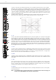
CMS3 sound. You should use the natural reproduction as an orientation mark and rely on your musically trained ear. The moderate use of the MID control is the best remedy to avoid acoustical feedback. Especially in this frequency range you should try to avoid excessive enhancement. Lowering the level more or less in this band will provide you with high amplification rates without feedback. Use the LO control according to your pleasing, to add more “punch” to the sound of a kick drum or “body” to the vocals.
CMS3 11 - PFL Engaging the PFL button routes the audio signal to the headphones bus, so that it is present at the phones output connector. The meter instrument in the master section is simultaneously switched, so that the left LED-chain indicates the level of the actually chosen channel (in dBu), which allows optimally matching the level of the signal source.
CMS3 2.2 Input Stereo Since most features – AUX/MON controls and channel faders – of the STEREO INPUTS are virtually identical to the ones of the MONO INPUTS we will not discuss their functioning in detail again. Thus, in the following we only point out the differences and like to ask you to refer to the analogous paragraphs within this owner’s manual describing the mono inputs. HINT: The stereo inputs 5-6 and 7-8 are designed as so-called Super Channels.
CMS3 achieved at the 0 dB mark. The control offers level reduction of -10 dB and an amplification of +20 dB. This range allows the connection of most professional, semi professional, and hi-fi sound sources. For further details on how to set the TRIM LINE CD control, please refer to the description of the GAIN control in monaural channels. 16 - EQ SECTION The EQ section of the input stereo is identical to the EQ section of the input mono.
CMS3 2.3 FX 1/2 The CMS offers two independently controllable, identically configured 24-bit stereo effect units – FX 1 and FX 2. Each unit provides 100 program presets, which are selected by the use of the UP/DOWN buttons. Parameters of presets can be edited and stored as User Preset (101 - 120), see page 22 for details. The 100 presets are divided into groups according to their different effect structure, as shown on a printed listing.
CMS3 The two effect programs are equally suitable for live performance or recording applications and can be used separately or together. For testing, evaluating and selecting effect programs, please also refer to the preset table on page 25, which provides detailed description of all effect presets. This listing contains all preset names together with the corresponding effect structure, field of application, and frequency characteristics.
CMS3 14
CMS3 2.4 AUX Generally, the AUX channel is used for the connection of an additional, external FX unit. Depending on the setting of the AUX 1/2 POST button, it is also possible to configure the bus for monitoring purposes. Additionally the AUX channel is available at the DIGITAL AUDIO INTERFACE (channel USB 3). 30 - AUX SEND This output provides connection for an external FX unit or, when used for monitoring, a power amplifier or active stage monitor speaker systems.
CMS3 16
CMS3 38 - MASTER LED-DISPLAY The CMS offers two 10-segment LED-chains for optical monitoring the output levels of the L/R master signals. The indication range of the LED-meter is 40 dB, indicating the levels that are present at the master outputs in dBu. The meter’s 0 dB mark is referenced to a 0 dBu output signal at the mixer output. As soon as a PFL button is engaged, the PFL LED lights.
CMS3 18
CMS3 47 - PHONES This control sets the volume of the headphones connected. CAUTION: Make sure to set the control to its minimum position before connecting headphones. Permanent hearing loss may occur if headphones are used at high volume. 48 - REC SEND L/R These RCA-type connectors carry the pre fader master L/R signal. The signal is not affected by the setting of the master faders and therefore mostly used for the connection of MD or flash recorders for recording purposes.
CMS3 Menu mode Press the MENU/ENTER rotary encoder in effect mode to enter the menu mode. In menu mode the display indicates the function being executed for each function key. 53 - MENU/ENTER Use the MENU/ENTER rotary encoder in menu mode for menu navigation. In effect mode the MENU/ENTER rotary encoder has no function. 54 - TAP If a delay effect is used the delay time can be adjusted to the beat by pressing the TAP button multiple times. The yellow LED indicates the delay time set.
CMS3 3 Display & functions The CMS includes a premium OLED display. Compared to general LC displays the OLED display is brighter, has a greater contrast ratio and a wider viewing angle. 3.1 Effect mode The start screen appears after switching the CMS on. After a few seconds the default effect for FX 1 & FX 2 and other system parameters are displayed.
CMS3 MENU STRUCTURE Illustration 3-5: Menu structure of CMS PLAY 11-12 MIDI BRIGHT HALL 5 PEAK AUX MONO DELAY Main Menu 55 Large Hall 3 230 ms 40% FX1 FX2 Edit FX 1 Device Setup FX Control Setup Footswitch Ctrl. Edit FX 2 Display Brightness TAP Button Ctrl.
CMS3 This dialog is used to change the user preset‘s description. Turn the MENU/ENTER rotary encoder to the left or right to edit the highlighted character. Pressing the MENU/ENTER rotary encoder accepts the desired symbol and moves the cursor to the next character. Move the cursor to the left or to the right by pressing the or function keys. Select the symbol or press the OK function key to quit editing the name. Pressing the BACK function key returns to the menu.
CMS3 Parameter Description ENTER rotary encoder to apply the selected brightness. Pressing the BACK function key returns to the menu. Pressing the ESC function key returns to effect mode. Footswitch Ctrl. Select FX 1, FX 2 or FX 1+2 to control one or both effect units using a footswitch. Screensaver TAP Button Ctrl. Select FX 1, FX 2 or FX 1+2 to control the delay time of one or both effect units using the TAP button.
CMS3 ed, pressing the MENU/ENTER rotary encoder resets the CMS to its factory settings. If NO has been selected, all parameters stay unchanged and the display returns to the menu. Pressing the BACK function key returns to the menu. Pressing the ESC function key returns to effect mode. Table 3-15 lists all parameters that are affected by a reset. Firmware Info Press the MENU/ENTER rotary encoder to open the Firmware Info dialog.
CMS3 4 DIGITAL AUDIO INTERFACE The USB 2.0-Port of the CMS serves as digital audio interface for the connection of a PC or Apple Macintosh (Mac). The DIGITAL AUDIO INTERFACE can be used as input or output device at the same time. When using a PC/ Mac with USB 2.0 interface up to four channels can be transmitted simultaneously in any direction. When using a PC/Mac with USB 1.1 interface up to two channels can be transmitted simultaneously in any direction. HINT: Using high grade USB 2.
CMS3 4.3 Status display selection of suitable MIDI channels, see also “FX Control Setup” on page 23 and the documentation of your software application. In effect mode, the display of the CMS shows the status information of the DIGITAL AUDIO INTERFACE.
CMS3 4.6 Example of usage (Recording) In the following application, your PC/Mac is used for recording while the CMS functions as premium A/D converter, without the need for an external sound card. LIVE-RECORDING OF EVENTS The mixer master signal is transmitted to the PC on USB channels 1-2 of the DIGITAL AUDIO INTERFACE. This is the basic setting for a live recording of your event. On USB channel 3 (or 4) the AUX (or MON) way is transmitted to the PC.
CMS3 5 Setting up a standard PA 5.1 Cabling The mains supply cord comes with the CMS. The quality of all other cables lies in your responsibility. Carefully chosen high quality cables are the best precaution to prevent later problems during live operation. The following wiring alternatives are recommended to provide trouble free operation of your system.
CMS3 4. 5. 6. between the two speaker “clusters” – the more compact the sound. Try to avoid the positioning of the main loudspeakers behind the imaginary line of microphones. Otherwise, if you have to drive the system at higher sound levels, the risk of feedback is very likely. After you have installed all microphone stands and all artists found their place, the best spot to install the monitor speakers is up front facing the musicians and vocalists.
CMS3 MONITOR MIX 1. 2. 3. Set the MON fader located in the master section to the -5 dB mark. Set the MON controls of all input channels according to your personal taste. Use the FX 1/2 to MON control to add the effect mix to the monitor mix, without influencing the master mix. Normally, the monitor mix needs less FX than the master mix. FINE TUNING Let the artists perform and check the sound of the system from different angles and distances.
CMS3 6 Setup examples 6.
CMS3 6.
CMS3 6.
CMS3 6.
CMS3 6.5 CMS with CORUS-Evolution system Illustration 6-5: CMS with CORUS-Evolution system (2 x C 25.2, 2 x Sub 2.
CMS3 37
CMS3 WICHTIGE SICHERHEITSHINWEISE Das Blitzsymbol innerhalb eines gleichseitigen Dreiecks soll den Anwender auf nicht isolierte Leitungen und Kontakte im Geräteinneren hinweisen, an denen hohe Spannungen anliegen, die im Fall einer Berührung zu lebensgefährlichen Stromschlägen führen können. Das Ausrufezeichen innerhalb eines gleichseitigen Dreiecks soll den Anwender auf wichtige Bedienungs- sowie Servicehinweise in der zum Gerät gehörenden Literatur aufmerksam machen. 1. 2. 3. 4. 5. 6. 7. 8. 9. 10. 11.
CMS3 1 Einführung Das Compact Mixing System CMS 600-3 ist ein professionelles Mischpult das aufgrund der vielen integrierten Features, wie Equalizer und Effektgeräte, eine optimierte Komplettlösung für unterschiedlichste Einsatzgebiete darstellt. Das CMS-Pult kann äußerst zeitsparend und einfach aufgebaut werden, da komplizierte Rack-Konfiguration und störanfällige Verkabelung mehrerer Einzelgeräte entfallen.
CMS3 2 Bedienelemente und Anschlüsse 2.1 Input Mono HINWEIS: Achten Sie bitte darauf, dass vor dem Anschluss von Signalquellen die jeweiligen Kanalregler, mindestens jedoch die beiden Masterregler, geschlossen sind, oder der STANDBY-Schalter gedrückt ist. Sie ersparen sich selbst, Ihrem Publikum und Ihrem Equipment unnötige Beanspruchungen durch Knackgeräusche.
CMS3 HINWEIS: Betreiben Sie bitte keine E-Gitarre bzw. E-Bass mit passiver Elektronik und hochohmigem Ausgang direkt an einem Mischpult LINE-Eingang. Diese Eingänge sind typischerweise, auch bei allen andern Herstellern, für relativ niedrige Quellimpedanzen ausgelegt, wie sie elektronische Geräte aufweisen. Das Klangergebnis wird unbefriedigend sein und der Klangcharakteristik der Instrumente nicht gerecht werden.
CMS3 5 - KLANGREGELUNG (HI-, MID-, LO-REGLER) Die Klangregelung erlaubt eine sehr umfangreiche und effektive Beeinflussung des Eingangssignals innerhalb unterschiedlicher Frequenzbereiche. Eine Drehung der Klangregler nach rechts bewirkt eine Anhebung/Verstärkung des entsprechenden Frequenzbereichs. Eine Drehung nach links bewirkt eine Absenkung/Abschwächung des entsprechenden Frequenzbereichs. Bei der Klangeinstellung sollten Sie immer von der Neutralstellung ausgehen, d. h.
CMS3 9 - PAN-REGLER Dieser Regler bestimmt die räumliche Position des Eingangssignals im Stereobild. In Mittelstellung wird das Signal zu gleichen Teilen auf die beiden Summen L und R aufgeteilt. Die PAN-Regler-Stufe ist so ausgelegt, dass egal wo Sie den PAN-Regler hindrehen, die Gesamtlautstärke im Stereo-Klangbild erhalten bleibt. 10 - MUTE-SCHALTER Der MUTE-Schalter schaltet das Eingangssignal ab dem Kanalschieberegler, einschließlich des AUX SEND- und MONITOR-Ausgangs, stumm.
CMS3 2.2 Input Stereo Viele Funktionsgruppen wie AUX-Regler, MON-Regler und Fader sind im Stereo-Eingang identisch zum Mono-Eingang aufgebaut und wurden dort bereits ausführlich erklärt. Wir wollen hier nur die wesentlichen Unterschiede herausarbeiten. Ansonsten dürfen wir Sie auf den jeweiligen Abschnitt im Kapitel Input Mono verweisen. HINWEIS: Die Stereo-Eingänge 5-6 bzw. 7-8 sind als sogenannte Super-Channels ausgeführt.
CMS3 15 - TRIM LINE CD-REGLER Mit diesem Regler wird das Signal an den Klinken-Eingängen bzw. Cinch-Eingängen im Stereokanal an den internen Arbeitspegel des Mischpultes angepasst. Der Regelbereich liegt bei 30 dB. Die Unity-Gain-Position, also 0 dB Durchgangsverstärkung, ist hier bei der Markierung 0 dB. Sie können mit diesem Regler das Signal um bis zu 10 dB abschwächen bzw. um bis zu 20 dB verstärken.
CMS3 2.3 FX 1/2 Das CMS ist mit zwei unabhängig regelbaren 24bit-Stereo-Effektteilen FX 1 und FX 2 ausgestattet. Die beiden Effektteile sind völlig identisch aufgebaut. Es stehen je Effektsektion 100 Presets zur Auswahl, die über das Display selektiert werden. Darüber hinaus besteht die Möglichkeit ausgehend von den Preset-Programmen einzelne Parameter der Effekte zu verändern und in 20 User-Presets (Programmnummer 101-120) abzuspeichern.
CMS3 2. 3. 4. Mit der DOWN-Taste (links) schalten Sie die Presets in absteigender Reihenfolge durch, mit der UP-Taste (rechts) in aufsteigender Reihenfolge. Wenn Sie länger auf eine dieser Tasten drücken, können Sie dadurch einen schnellen Vor- bzw. Rücklauf der Programmnummern erzeugen. Die Effektgruppen sind größtenteils in 10er-Schritten eingeteilt. Wenn Sie beide Tasten eines Effektteils gleichzeitig drücken, wird der erste Effekt der nächsten Effekt-Gruppe aufgerufen.
CMS3 48
CMS3 2.4 AUX Der Kanalzug AUX kann beliebig zum Monitoring oder als FX Send (bei Wahl von AUX POST) betrieben werden. Zusätzlich ist AUX auf dem Aufnahmekanal 3 des DIGITAL AUDIO INTERFACE verfügbar. 30 - AUX SEND-BUCHSE Hier schließen Sie entweder ein Effektgerät oder im Monitorbetrieb eine Monitorendstufe bzw. einen Aktivmonitor an. Der Pegel an dieser Buchse kann in einem weitem Bereich bis maximal +20 dBu über den AUX-Fader geregelt werden.
CMS3 50
CMS3 38 - MASTER-AUSSTEUERUNGSANZEIGE Die Aussteuerungsanzeige des CMS besteht aus zwei LED-Ketten für den rechten bzw. linken Kanal mit je 10 LEDs pro Kette. Der Anzeigebereich liegt bei 40 dB und stellt den Pegel in dBu an den Master-Ausgängen dar. D.h. zeigt die Anzeige 0 dB an, so stehen am Mischpultausgang aktuell 0 dBu. Sobald einer der PFL-Schalter gedrückt ist, leuchtet die gelbe PFL-LED. Die linke LED Kette zeigt nun den Arbeitspegel im ausgewählten Kanal.
CMS3 52
CMS3 46 - PHONES-BUCHSE Diese Stereo-Klinkenbuchse (6,3 mm) ist für Kopfhörer von 32 bis 600 Ohm geeignet. Hier kann das PFL-Signal abgehört werden, wenn eine PFL-Taste gedrückt ist. Ist keine PFL-Taste gedrückt, führt der PHONES-Ausgang das MASTER A L/ R-Signal. Da der Ausgang kurzschlussfest ist, können Sie auch Kopfhörer oder InEar-Monitorsysteme mit einer Impedanz unter 32 Ohm anschließen. Dies führt aber unter Umständen zu einer Reduzierung der maximal erreichbaren Lautstärke.
CMS3 2.7 DISPLAY mit Funktions-Tasten 52 - DISPLAY MIT 4 FUNKTIONSTASTEN Zum Schutz vor Verkratzen ist das Displayglas bei Auslieferung mit einer Folie abgedeckt. Ziehen Sie diese bitte ab. Effekt-Betriebsart Das Display zeigt in der Effekt-Betriebsart die aktuell eingestellte Programmnummer des jeweiligen Effektteils an. Mit den vier Tasten unter dem Display werden die Effektprogramme angewählt. Weitere Informationen finden Sie im Abschnitt “Effekt-Betriebsart” auf Seite 56.
CMS3 56 - NETZSCHALTER (POWER) Netzschalter zum Ein- und Ausschalten des Gerätes. Das Gerät ist betriebsbereit, wenn das Display aufleuchtet. Achten Sie bitte darauf, dass beim Anschalten des Gerätes die beiden MASTER-Fader geschlossen sind, oder der STANDBYSchalter gedrückt ist. Sie ersparen sich selbst, Ihrem Publikum und Ihrem Equipment unnötige Beanspruchungen durch ungewollte Signalverstärkung oder sogar Rückkopplungen. Für angeschlossene Leistungsverstärker und andere elektronische Geräte, wie z. B.
CMS3 3 Display & Funktionen Das CMS ist mit einem hochwertigen OLED-Display ausgestattet. Im Vergleich zu üblichen LC-Displays sind OLED-Displays wesentlich heller, kontrastreicher und sind unabhängig vom Blickwinkel optimal abzulesen. 3.1 Effekt-Betriebsart Nach dem Einschalten des CMS wird der Startbildschirm angezeigt. Nach einigen Sekunden werden die momentan aktiven Effekte der Effektteile FX 1 bzw. FX 2 und weitere, wichtige Informationen angezeigt.
CMS3 MENÜ-BAUM Abbildung 3-5: Menüstruktur des CMS PLAY 11-12 BRIGHT HALL MIDI PEAK AUX MONO DELAY 5 Main Menu 55 Large Hall 3 230 ms 40% FX1 FX2 Edit FX 1 Device Setup FX Control Setup Footswitch Ctrl. Edit FX 2 Display Brightness TAP Button Ctrl.
CMS3 Im Set FX Name Dialog kann die Bezeichung des User Presets eingegeben werden. Drehen Sie den MENU/ENTER-Drehencoder nach links oder rechts, um das mit dem Cursor markierte Zeichen zu ändern. Drücken des MENU/ ENTER-Drehencoders übernimmt das gewählte Zeichen und bewegt den Cursor um eine Stelle nach rechts. Mit den Funktionstasten bzw. kann der Cursor nach links bzw. rechts bewegt werden. Wählen Sie das Zeichen oder drücken Sie die Funktionstaste OK um die Eingabe zu beenden.
CMS3 Im FX Control Setup Dialog kann durch Drehen des MENU/ENTER-Drehencoders ein Eintrag in der linken Spalte markiert und durch Drücken des MENU/ENTERDrehencoders der entsprechende Wert in der rechten Spalte ausgewählt werden. Der ausgewählte Wert wird nun durch Drehen des MENU/ENTER-Drehencoders angepasst und der neue Wert durch Drücken des MENU/ENTER-Drehencoders übernommen. Folgende Tabelle erläutert die Einträge des FX Control Setup Dialogs. Drücken der BACK-Funktionstaste führt in das Menü zurück.
CMS3 Play 11-12 at STDBY Um im STANDBY-Betrieb des CMS über den Eingang 1112 (bzw. CD 3-4) Hintergrundmusik einspielen zu können, wählen Sie hier den Eintrag „Enable“. HINWEIS: Bei Wahl von „Enable“ müssen Sie bei Aktivierung des STANDBY-Betriebs die Sicherheitsabfrage im Display (innerhalb von 5 Sekunden) durch Drücken MENU/ ENTER-Drehencoder bestätigen. bei Wahl von NO wird der Rücksetzvorgang abgebrochen. Drücken der BACK-Funktionstaste führt in den Device Setup Dialog zurück.
CMS3 4 DIGITAL AUDIO INTERFACE Die USB 2.0-Schnittstelle dient als digitale Audio-Schnittstelle des CMS für einen PC oder Mac. Das DIGITAL AUDIO INTERFACE kann gleichzeitig als Eingang und Ausgang verwendet werden. Verfügt Ihr PC/Mac über eine USB 2.0-Schnittstelle, können in jede Richtung vier Kanäle gleichzeitig übertragen werden. Bei Verwendung einer USB 1.1-Schnittstelle können in jede Richtung jeweils zwei Kanäle gleichzeitig übertragen werden. HINWEIS: Verwenden Sie hochwertige USB 2.
CMS3 Abbildung 4-1: Konfiguration von Cubase LE 4.3 Funktionsanzeige im Display Das Display des CMS zeigt in der Effekt-Betriebsart Statusinformationen des DIGITAL AUDIO INTERFACE an.
CMS3 Abbildung 4-4: Übertragung von MIDI-Daten vom PC/Mac zu einem Synthesizer (Abbildung zeigt CMS 1000-3) HINWEIS: Abbildung 4-5: Übertragung von MIDI-Daten von einem Master Keyboard zum PC/Mac (Abbildung zeigt CMS 1000-3) Sollen MIDI-Daten mit der Medienwiedergabe von Windows an externen Geräten wiedergegeben werden, müssen Sie in der Windows-Systemsteuerung den Dialog "Sounds und Audiogeräte" öffnen und das Standardgerät der MIDI-Musikwiedergabe auf DYNACORD USB-MIDI umstellen. 4.
CMS3 E-Gitarre) nur gering oder gar nicht auf die Beschallungsanlage gegeben werden. Umgekehrt klingen Aufnahmen, die nur über ein Raummikrofon gemacht wurden, sehr indirekt und lassen gerade beim Gesang Klarheit und Verständlichkeit vermissen. Das CMS bietet nun die Möglichkeit, beide Signalquellen (Mischpultausgang und Raummikrofon) getrennt voneinander aufzunehmen. Bei der Nachbearbeitung der Aufnahmen können Sie die beiden Anteile im optimalen Verhältnis aufeinander abstimmen.
CMS3 5 Aufbau einer Standard-PA 5.1 Verkabelung Das Netzkabel haben Sie mit dem CMS erhalten. Für alle anderen Kabel sind Sie selbst verantwortlich und je sorgfältiger Sie bei der Auswahl der Kabel vorgehen, um so weniger Probleme sind später im Einsatz zu erwarten. Wir können hier nur einige Empfehlungen geben mit denen Sie einen störungsfreien Betrieb Ihres Aufbaus erreichen.
CMS3 3. 4. 5. 6. schrauben oder, wenn dies nicht ausreichend ist bzw. keine Bassboxen benötigt werden, Hochständer. Stellen Sie die linke und rechte PA-Boxen-Kombination nur so weit auseinander wie nötig. Der Sound wird dadurch kompakter. Achten Sie darauf, dass die PA-Boxen der Hauptanlage wenn möglich nicht direkt hinter den Mikrofonen stehen, weil sonst bei höheren Lautstärken Rückkopplungspfeifen zu erwarten ist.
CMS3 Kanälen nur bei sehr hohen Dynamikspitzen aufleuchtet. Bei häufigem Aufleuchten drehen Sie die FX-Regler in allen beteiligten Eingangskanälen in etwa gleichem Maß zurück. MONITORMIX 1. 2. 3. Ziehen Sie den MON-Fader im Masterbereich auf die -5 dB Positon. Passen Sie den Monitormix über die MON-Regler in den belegten Eingangskanälen so an, dass die Abmischung der Klangquellen Ihrer Vorstellung entspricht.
CMS3 6 Aufbaubeispiele 6.
CMS3 6.
CMS3 6.
CMS3 6.
CMS3 6.5 CMS mit CORUS-Evolution System Abbildung 6-5: CMS mit CORUS-Evolution System (2 x C 25.2, 2 x Sub 2.
CMS3 7 Specifications Property CMS 600-3 Order No. F01U213891 DC-CMS600-3-UNIV Channels 4 +2 + 2 MIC/Line-Mono 4 MIC/Line-Mono / USB-Stereo (Super Channel) 2 Line L-R / CD-IN-Stereo 2 Auxiliarys (AUX, MON) Pre/Post switchable, Pre MIC GAIN (LINE -20 dB) +10 to +60 dB TRIM LINE/CD (Stereo) -10 to +20 dB THD, at 1 kHz, MBW = 80 kHz MIC input to Master A L/R outputs, +16 dBu, typical < 0.005% Frequency Response, -3 dB, ref.
CMS3 Property AD/DA Conversion Sampling Rate CMS 600-3 24-bit 44.1 / 48 / 88.2 / 96 kHz PC Interface USB2.
CMS3 7.
CMS3 7.
CMS3 Trademarks. • Microsoft, Windows, Windows XP, Windows Vista and Windows 7 are either registered trademarks or trademarks of Microsoft Corporation in the United States and/or other countries • Apple, Macintosh, Mac OS and Mac OS X are trademarks of Apple Inc., registered in the United States and other countries • Cubase is a registered trademark of Steinberg Media Technologies GmbH.
CMS3 Notes 78
CMS3 79
DYNACORD 12000 Portland Avenue South, Burnsville, MN 55337, USA Phone: +1 952/844-4051, Fax: +1 952/884-0043 www.dynacord.com © Bosch Communications Systems Part Number F01U250630 Vs 03 Europe, Africa, and Middle East only. For customer orders, contact Customer Service at: +49 9421-706 0 Fax: +49 9421-706 265 Asia & Pacific only.