
Owner`s manual
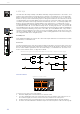


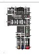
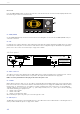
Table Of Contents
- 1 Introduction
- 2 Controls, Indicators and Connections
- 2.1 Input Mono
- 2.2 Input Stereo
- 2.3 FX 1/2
- 2.4 AUX
- 2.5 MON
- 2.6 MASTER with GEQ
- 37 - USB 2.0 DIGITAL AUDIO INTERFACE
- 38 - MASTER LED-DISPLAY
- 39 - STANDBY
- 40 - MASTER L/R fader
- 41 - MASTER A OUTPUTS L/R
- 42 - MASTER B OUTPUTS L/R
- 43 - MASTER B
- 44 - PRE/POST of MASTER B
- 45 - STEREO/MONO of MASTER B
- 46 - PHONES
- 47 - PHONES
- 48 - REC SEND L/R
- 49 - REC SEND & USB OUT
- 50 - 9-BAND STEREO GRAPHIC EQUALIZER
- 51 - USB INTERFACE
- 2.7 DISPLAY with function keys
- 2.8 Rear panel
- 3 Display & functions
- 4 DIGITAL AUDIO INTERFACE
- 5 Setting up a standard PA
- 6 Setup examples
- 1 Einführung
- 2 Bedienelemente und Anschlüsse
- 2.1 Input Mono
- 2.2 Input Stereo
- 2.3 FX 1/2
- 2.4 AUX
- 2.5 MON
- 2.6 MASTER mit GEQ
- 37 - USB 2.0 DIGITAL AUDIO INTERFACE
- 38 - MASTER-Aussteuerungsanzeige
- 39 - STANDBY-Schalter
- 40 - MASTER L/R-Fader
- 41 - MASTER A OUTPUTS L/R-Buchsen
- 42 - MASTER B OUTPUTS L/R-Buchsen
- 43 - MASTER B-Regler
- 44 - PRE/POST-Schalter für MASTER B
- 45 - STEREO/MONO-Schalter für MASTER B
- 46 - PHONES-Buchse
- 47 - PHONES-Regler
- 48 - REC SEND L/R-Buchsen
- 49 - REC SEND & USB OUT-Regler
- 50 - 9-BAND STEREO GRAPHIC EQUALIZER
- 51 - USB INTERFACE-Anzeige
- 2.7 DISPLAY mit Funktions-Tasten
- 2.8 Rückseite
- 55 - Netzbuchse
- Die Spannungsversorgung des CMS erfolgt ausschließlich mit dem mitgelieferten IEC-Netzkabel über eine verriegelnde Netzbuchse. Schließen Sie das CMS nur an eine geeignete Netzversorgung an, die den auf dem Typenschild angegebenen Anforderungen ent...
- 56 - Netzschalter (POWER)
- 57 - MIDI IN/OUT-Buchsen
- 3 Display & Funktionen
- 4 DIGITAL AUDIO INTERFACE
- 5 Aufbau einer Standard-PA
- 6 Aufbaubeispiele
- 7 Specifications

CMS
3
15
2.4 AUX
Generally, the AUX channel is used for the connection of an additional, external FX unit. Depending on the setting of the
AUX 1/2 POST button, it is also possible to configure the bus for monitoring purposes. Additionally the AUX channel is
available at the DIGITAL AUDIO INTERFACE (channel USB 3).
30 - AUX SEND
This output provides connection for an external FX unit or, when used for monitoring, a power amplifier or active stage
monitor speaker systems. Using the AUX fader allows setting the output level in a wide range up to +20 dBu. The AUX
SEND is designed in Ground Sensing technology to prevent the induction of external noise, even with long cables. Use
balanced cables for the connection of external components whenever it is possible.
31 - AUX PRE/POST/
TO FX 2
The current mode of the AUX channel is indicated by this LEDs. Please refer to page page 23 for more details about the
available modes.
32 - MUTE
The MUTE button mutes the AUX output signal.
33 - AUX
FADER
This fader controls the summed audio signal at the AUX output. When used for monitoring, this fader lets you control
the volume of the monitor system. When using the DIGITAL AUDIO INTERFACE for recording this fader also controls the
volume of the sent channel USB 3. See page 26 for details about using the DIGITAL AUDIO INTERFACE.
2.5 MON
34 - MONITOR
This output provides connection for an power amplifier or active stage monitor speaker systems. The MONITOR output
is designed in Ground Sensing technology to prevent the induction of external noise, even with long cables. Use bal-
anced cables for the connection of external components whenever it is possible. Additionally the MON channel is avail-
able at the DIGITAL AUDIO INTERFACE (channel USB 4).
35 - MUTE
The MUTE button mutes the MON output signal.
36 - MON
FADER
This fader controls the summed audio signal at the MONITOR output. When using the DIGITAL AUDIO INTERFACE as
output, this fader also controls the volume of sent channels USB 4.
2.6 MASTER with GEQ
37 - USB 2.0 DIGITAL AUDIO INTERFACE
The USB interface of the CMS is a USB B (female) connector. Please refer to chapter “DIGITAL AUDIO INTERFACE” on
page 26 for more details.